OK from the pictures the tubes are 12AY7, so that question is answered...
Confirms the old saying "he who knows how to read has an advantage" 😀
Confirms the old saying "he who knows how to read has an advantage" 😀

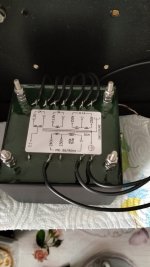
Your capacitors should not be conducting any heat or be hot to the touch. Have you unmounted it from the chassis to see if a similar problem occurs? I'm just wondering if you had a lead that may be contacting chassis? I had a similar issue initially (I didn't trim them too well initially).I had a strong doubt about the power supply connections 6.3-0 12.6 -0 shouldn't I reverse?
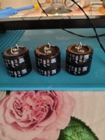
The 4700uf capacitors are very hot after half an hour on, the first two 8600uf capacitors are also slightly hot, is this normal?


It should not be an issue to my knowledge, as long as the heater is getting the needed voltage to warm up.
Hi guys, excuse me one question: A friend of mine brought me a Kondo KSL m77 preamp built without modifications some, to check, when I insert the Phono preamp I hear a very loud Uhmm that increases as the volume increases .... Has anyone had the same problem and how to solve it ? Thanks a lot to everyone
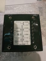
looks correct. Can you measure the AC voltages at each connection while the preamp is on ?Are the power connections right like this or do they need to be reversed?
6.3-0. 12.6-0
I don't want that to be the problem
Original or clone?Hi guys, excuse me one question: A friend of mine brought me a Kondo KSL m77 preamp built without modifications some, to check, when I insert the Phono preamp I hear a very loud Uhmm that increases as the volume increases .... Has anyone had the same problem and how to solve it ? Thanks a lot to everyone
My clone pretty much never had a hum problem. If it is a clone, you may want to check the connections between PCB ground and chassis ground...
the voltages are 6.8 13.3 AClooks correct. Can you measure the AC voltages at each connection while the preamp is on ?
My transformer is 100mA as requested on the power board
Thanks for the answer... yes it's the cloneOriginal or clone?
My clone pretty much never had a hum problem. If it is a clone, you may want to check the connections between PCB ground and chassis ground...
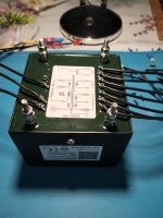
Values taken between MJ3000 (frame) and PIN test 12.6So, 14.3V without the tubes, and 11.8V with tubes? hmmm....... The collector voltage (which is the incoming rectified AC) can be measured from the metallic case of the MJ3000 to the test points on the PCB (the two points where it says 12.6V) - it should show something small to one point (~3V) and 15...16V to the other.
That would indicate that the traces on the PCB are too small, and you may want to put cables in parallel to reduce the voltage drop there. This is strange, because most other PCBs seem to not show the problem.
Are you using 12AY7 with 300mA heater current?
13.1v 1.28v DC
Were you able to fix a 500R resistor in place of the variable? the numbers don't seem too off. In other news, I have another clone on my test bench. Will be putting this one together as a favor for a close friend. Keep everyone posted, may try different parts to hear any audible differences.
The problem remains, I made a few measurements on hesener advice, tomorrow if I can I'll try to go over some welding again, you never know
This means the incoming DC voltage is 13.1V, and the transistor drops 1.28V. This is way too small. The incoming voltage should be higher (~15V) so the transistor drops ~2V, to have ~13V on the output. This also means the transistor is not operating correctly and cannot regulate the voltage.Values taken between MJ3000 (frame) and PIN test 12.6
13.1v 1.28v DC
Can you please try and measure the AC voltage on the transformer connections (where it says 12.8V), with all tubes ON ? I think we are coming close..

- Home
- Amplifiers
- Tubes / Valves
- Kondo KSL-M77 phono preamp clone project