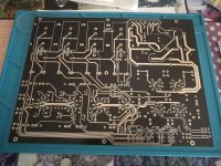
Hi Derek, I'm attaching some photos
Attachments

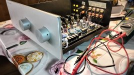


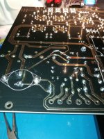
Another photo
Attachments
-
 IMG20230410213115.jpg342.1 KB · Views: 145
 -
 IMG_20220425_180115.jpg346.5 KB · Views: 138
 -
 IMG_20220514_235519.jpg264.9 KB · Views: 146
 -
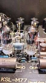 image.jpg333.1 KB · Views: 161
 -
 IMG_20220514_232736.jpg367.7 KB · Views: 146
 -
 IMG20230410210801.jpg336.1 KB · Views: 155
 -
 IMG20220824215007.jpg312.5 KB · Views: 156
 -
 IMG_20220504_105549.jpg324.2 KB · Views: 142
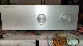
I also used the 10k resistor across the inputs as well, don't have issues with any popping or noise coming through the speakers. Only hear the clicking of the relays.I have used my M77 for a while now and I'm very pleased with it. The only issue left is that there is a bit of noise when switching between inputs. Do any of you have this problem? And perhaps a solution?
Thanks for the compliments, I have to solve the problem of the voltage difference between the line and the phono. Let's hope so 👍
Hi all, I'm trying to solve the voltage problem I have between line and phono.
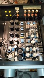
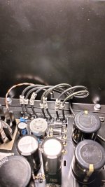
On the test point with the selector on phono I have 11.6v while with the selector on line I have 13.1v. I don't understand what could be the problem. I noticed that the two 4700uf capacitors are pretty hot after half an hour on, is this normal?
Thank you.
On the test point with the selector on phono I have 11.6v while with the selector on line I have 13.1v. I don't understand what could be the problem. I noticed that the two 4700uf capacitors are pretty hot after half an hour on, is this normal?
Thank you.
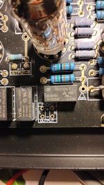
The value of the trimpot resistor is so minimal I could not really measure out much difference either, I recall others have mentioned replacing it with a fixed resistor. I did not notice the pair of 4700uF being warm, however, I did notice the 2k resistor right before the choke being slightly warm to the touch.
Penso che il pericolo sia molto piccolo, la maggior parte delle sorgenti non ha problemi di cortocircuito sull'uscita, specialmente quando non c'è segnale. Discorso diverso per gli amplificatori di potenza😀
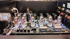
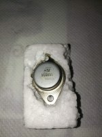
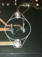
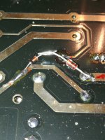
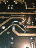
Sì, quella differenza di tensione è strana.... L'MJ3000 e il 2N3055 (usato prima) hanno lo stesso pinout, quindi non puoi davvero inserirlo nel modo sbagliato. L'emettitore di quel transistor è l'alimentazione del riscaldatore per tutte le valvole, quindi dovrebbero avere tutte la stessa tensione del riscaldatore.
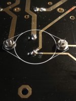
Forse potresti misurare la resistenza tra gli stessi punti sui tubi (collegamento del riscaldatore), per vedere se le tracce sono a bassa resistenza? (il pin4 di ogni tubo al pin 4 degli altri tubi, lo stesso per il pin5 al pin5). Solo per vedere se c'è forse un problema con le tracce PCB.....
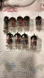
Inoltre, potresti provare a scambiare le valvole tra la sezione phono e quella di linea, solo per vedere se una delle valvole ha un problema....
Hi Hesener, I cleaned the paste from the MJ 3000 transistor pinout, I swapped the tubes as you suggested, I detected the values on the sockets without the tubes, and the value was 14.3v DC if I remember correctly.
How come the values on the sockets without valves are all the same, and with the valves mounted, no? So the problem is right after the transformer's AC input?
I had also checked the diode of your modification under the board and it was 14v. You told me to also check the value of the collector, but I don't know how to measure.
You also gave me the formula to get 12.6v, but I can't find the posts we exchanged anymore.
Thanks for the attention.
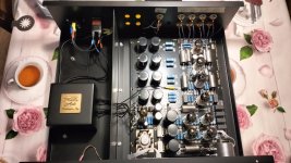
So, 14.3V without the tubes, and 11.8V with tubes? hmmm....... The collector voltage (which is the incoming rectified AC) can be measured from the metallic case of the MJ3000 to the test points on the PCB (the two points where it says 12.6V) - it should show something small to one point (~3V) and 15...16V to the other.
That would indicate that the traces on the PCB are too small, and you may want to put cables in parallel to reduce the voltage drop there. This is strange, because most other PCBs seem to not show the problem.
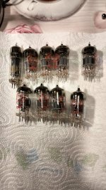
Are you using 12AY7 with 300mA heater current?
That would indicate that the traces on the PCB are too small, and you may want to put cables in parallel to reduce the voltage drop there. This is strange, because most other PCBs seem to not show the problem.
Are you using 12AY7 with 300mA heater current?
I have 11.8v when I set the selector to phono, 13.3 on line, I took the values from the 12.6v test point
I also swapped the valves but nothing changes, can you tell me what you mean by manifold?
Heating current 300mA?
Excuse me but I don't understand, am I inexperienced as regards the measurements?
I also swapped the valves but nothing changes, can you tell me what you mean by manifold?
Heating current 300mA?
Excuse me but I don't understand, am I inexperienced as regards the measurements?
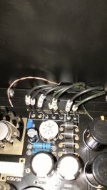
I had a strong doubt about the power supply connections 6.3-0 12.6 -0 shouldn't I reverse?
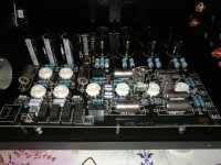
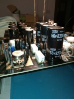
The 4700uf capacitors are very hot after half an hour on, the first two 8600uf capacitors are also slightly hot, is this normal?
The 4700uf capacitors are very hot after half an hour on, the first two 8600uf capacitors are also slightly hot, is this normal?
Attachments


I have 11.8v when I set the selector to phono, 13.3 on line, I took the values from the 12.6v test point
I also swapped the valves but nothing changes, can you tell me what you mean by manifold?
Heating current 300mA?
Excuse me but I don't understand, am I inexperienced as regards the measurements?
The tubes that should be used in this preamp is the 12AY7, and it has 300mA of heater current as per its datasheet. This is what the heater circuit is designed for (8 tubes x 300mA = 2.4A in total). So my question is: Are you using 12AY7?
The 12.6V test point has two connections. Can you please measure the voltage from both connections to the metal case of the MJ3000, with input selector set to phono? That would be very helpful.
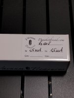
The capacitors should not heat up at all, this is strange.....If you can, please measure the voltages across each capacitor and compare with the rated voltage printed on the cap.
Don't worry we will get your preamp working fine!
- Home
- Amplifiers
- Tubes / Valves
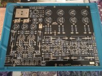
- Kondo KSL-M77 phono preamp clone project