I must respectfully disagree. The servo in the posted circuit does null DC low frequency content and DC, but the same mechanisms take subsonic content in the output and inject it back into the signal chain. Assuming equal “control authority,“ all servos will have similar behavior re failure. Susceptibility to capacitor distortion should also be comparable.Why put the servo in the audio path at all ? I feed my servo back to the LED CCS's. (below). It's also fault proof in case of servo failure.
OS

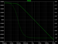
I Agree , <5hz .... there is degenerative FB - reducing loop gain by a few db as you approach the the F3 of the servo.I must respectfully disagree. The servo in the posted circuit does null DC low frequency content and DC, but the same mechanisms take subsonic content in the output and inject it back into the signal chain. Assuming equal “control authority,“ all servos will have similar behavior re failure. Susceptibility to capacitor distortion should also be comparable.
I use this on my Spooky (Leach amp) and my CFA above.
Here , just simulate it. (below). It works excellent in the real world - I've built it. Typically uV offset. Allows me to not worry about servo/cap quality ,
NFB fully cancels any AC component of the servo signal ,same as if it was rail ripple.
PS - the CCS is not really the audio path. On the other hand, If you are dealing with a PPM amp - Everything ,the rails and even the traces ... are in the audio path. That is - short of an ideal simulated power supply.
Attachments
This is from memory, the boards are back in NJ and I am in OH.Hi jacking,
Do you have a schematic you can post? I bet it’s possible to retrofit with modern FET opamp and film caps.
Attachments

Thanks, jackinnj!
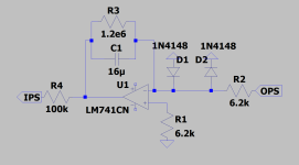
So you could impedance scale C1 and R2 to yield 1uF and 100k or even 0.1uF and 1M; I’d delete R3 to yield a pure integrator. You’d end up with the same settling time as the existing circuit. You’d swap the 741 to a TL071 or similar FET opamp. I’d set R1 to 0, but if you want to be a purist, you’d set R2 = R2 to match bias current errors; if you do this, bypass R1 with 0.1uF, ceramic OK here since there no AC present. C1 should be film cap or COG caps are available in 0.1uF. COG caps have superb distortion performance.
Do you recall where R4 injects into the amp and the associated resistors, and AC gain setting resistors? That’s a lot to recall from memory. 😉
PS I endorse Tomchr technique with X7R ceramic caps and believe it’s clever. Better dielectrics maybe be the easier path here in tems of installation. And Elvee’s early suggestion a great preamble experiment.
Last edited:
Noise bursts and or piezolectric effects may not be PSS so may not show up as HD/IMD? Does that mean there is no possible effect on the audio? Not so sure myself.Fantastic! Now just show how that impacts the output of an amp if those capacitors are used in a DC servo.
However, do accept polyester can work okay in a servo if the corner frequency is low enough.
Piezo-electric effects would show if someone pushed on the circuit board during operation similar to what's shown in the TI app note. I don't know what @indra1's argument is. That vibrations from the music being reproduced could make it into the amp and shake the capacitors in the DC servo to the point where they contribute audibly to the output of the amp? Sure. You can think up a scenario like that, but how big of an impact does it have, if any.
If the music is inducing a piezo-electric voltage in the ceramic capacitors and this voltage impacts the output of the amp I would expect the impact to show up as harmonic distortion. It would certainly be periodic, steady-state.
Tom
If the music is inducing a piezo-electric voltage in the ceramic capacitors and this voltage impacts the output of the amp I would expect the impact to show up as harmonic distortion. It would certainly be periodic, steady-state.
Tom
Don't know. For myself, I wouldn't necessarily trust that any noise would be PSS, or necessarily PSS enough to give a reliable spur level. Might depend on things like if the PCB had a mechanical resonant frequency? Anyway, recently read a forum post where a member described listening to notched distortion residuals. Seemed like it might be useful some some cases. Getting back to servos, I have listened to servo outputs before. Guess if I were thinking of using a ceramic cap I might try listening there and tapping on the cap or vibrating it get some idea if I trust it or not. Haven't tried it is all.how big of an impact does it have, if any.
You can certainly do that. But do you normally tap the capacitors in your amp when you listen to music? If you don't then I question the external validity of that experiment.
Tom
Tom
Depends, active speaker and car amplifier would be some of the bad place.how big of an impact does it have
As servo cap, effect won't show on THD+N into dummy load, no mechanical vibration.If the music is inducing a piezo-electric voltage in the ceramic capacitors and this voltage impacts the output of the amp I would expect the impact to show up as harmonic distortion.
Not normally, but I might if troubleshooting. When testing out something I am uncertain about, I don't consider attempts at provoking symptoms to be inappropriate. If I do find out there is some sensitivity, then I can assess whether or not I think it would ever matter....do you normally tap the capacitors in your amp when you listen to music?
For what it's worth, there was a thread somewhere where someone measured a DAC output spectrum with an LT3042 or LT3045 reference regulator. Using a ceramic class 2 capacitor for reference filtering, the sideskirts were much worse than with another type of capacitor, until the board was very carefully mechanically shielded against vibrations. He didn't tap anything and he measured it at home, not in a car or a fighter jet.
Edit:
https://www.diyaudio.com/community/threads/phase-noise-in-ds-dacs.387862/post-7063038
It was subsonic noise that it picked up, though. But that was in quiet surroundings.
Edit:
https://www.diyaudio.com/community/threads/phase-noise-in-ds-dacs.387862/post-7063038
It was subsonic noise that it picked up, though. But that was in quiet surroundings.
Last edited:
This is from memory, the boards are back in NJ and I am in OH.
Thanks, jackinnj!
So you could impedance scale C1 and R2 to yield 1uF and 100k or even 0.1uF and 1M; I’d delete R3 to yield a pure integrator. You’d end up with the same settling time as the existing circuit. You’d swap the 741 to a TL071 or similar FET opamp. I’d set R1 to 0, but if you want to be a purist, you’d set R2 = R2 to match bias current errors; if you do this, bypass R1 with 0.1uF, ceramic OK here since there no AC present. C1 should be film cap or COG caps are available in 0.1uF. COG caps have superb distortion performance.
I would use a FET op-amp, scale impedance as recommended by BSST, set R1 to 0 and scale R3.
R1 makes sense with a bipolar op-amp without base current compensation, but with a FET op-amp, it only adds noise. Bypassing it with a capacitor mitigates that, but not as effectively as shorting it.
I don't know the purpose of R3, but it could be that whoever put it there had a good reason for doing so. Hence my preference for scaling it. Maybe it has something to do with ensuring that the initial conditions during power up are predictable? Just guessing.
Mind you, as long as the loudspeakers and the room and the microphony of the capacitors are linear, microphony of DC loop capacitors that pick up some of the loudspeaker signals will only cause frequency response deviations, presumably small ones. When they pick up other sounds, those may be reproduced through the loudspeakers, but presumably much softer than ordinary room reflections. In a DAC reference, it would cause second-order distortion and sidebands, respectively.
I’d delete R3 to yield a pure integrator. You’d end up with the same settling time as the existing circuit.
I don't know the purpose of R3, but it could be that whoever put it there had a good reason for doing so. Hence my preference for scaling it. Maybe it has something to do with ensuring that the initial conditions during power up are predictable? Just guessing.
Isn't R3 added by jackinnj to determine the DC operating point only in the simulation? I don't think it exists in the actual circuit.
- Home
- Amplifiers
- Solid State
- Is your servo ruining the sound?