I have a Sumo Polaris which I have used for several years. Sounds great for a few months, then sounds annoying. Bias is fine and THD adjust pot all where they should be.
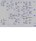
I wonder if the problem is in the servo which uses a 16uF integrating NP electrolytic capacitor and an (eek) LM741 operational amplifier, a Nat Semi original. Cordell, in both editions of his book has written extensively on servo's, reminding that the servo is in the signal path. Perhaps the electrolytic cap is suffering some inconsistent leakage issue, perhaps the RC-time constant of the servo is much too great.
I wonder if the problem is in the servo which uses a 16uF integrating NP electrolytic capacitor and an (eek) LM741 operational amplifier, a Nat Semi original. Cordell, in both editions of his book has written extensively on servo's, reminding that the servo is in the signal path. Perhaps the electrolytic cap is suffering some inconsistent leakage issue, perhaps the RC-time constant of the servo is much too great.
Hi jacking,
Do you have a schematic you can post? I bet it’s possible to retrofit with modern FET opamp and film caps.
Do you have a schematic you can post? I bet it’s possible to retrofit with modern FET opamp and film caps.

To test whether your hypothesis is right, you can put the servo out of service, replacing the opamp output with a potentiometer adjusted to get a ~zero offset (without any speaker connected, obviously).
When it is done, reconnect the speaker and try another listening test to assess the changes, if any.
If you notice improvements, it is probably time to consider BSST's advices
When it is done, reconnect the speaker and try another listening test to assess the changes, if any.
If you notice improvements, it is probably time to consider BSST's advices
Or ceramic caps. X5R, X7R, X8R work great for servos as long as you keep the voltage across them low.I bet it’s possible to retrofit with modern FET opamp and film caps.
I've not noticed any negative effects of using a well-designed servo. You do need to either use a high-order filter or push the cutoff frequency far down to avoid having the servo muck up the THD at 20 Hz, though.
Tom
Perhaps Marcel was referring to the 16uF NP Electrolytic cap, which after years is probably wonky. The polyesters for the most part are those less expensive variety which you used to get from Mouser 30 years ago.
The Sumo Polaris had a horrible review in Stereophile....the servo AND anti-distortion circuitry may have something to do with this.
Gents, as always, thanks for the input.
The Sumo Polaris had a horrible review in Stereophile....the servo AND anti-distortion circuitry may have something to do with this.
Gents, as always, thanks for the input.
I remember one of the Audio guys from the DEC forum writing about this about then, after convincing himself the servos are in the signal path. He wrote something like "See Walt ripping out all the electrlytics from his servos and replacing them..."30 years ago.
I met a guy at a hifi store in Copenhagen some 25ish years ago. He was very proud of his modified CD player. He'd removed all plastic from the components, including the plastic insert in the RCA connectors, the plastic sleeving on electrolytic capacitors, etc. He'd even replaced the power cord with some silk insulated lamp cord from the 1930s. After all, plastic is an inorganic material so therefore it sounds bad if it's in the signal path. And everything is in the signal path. I'm not sure how he managed to convince himself of this given that the CDs are made of ... plastic. Humans are not rational critters.
The DC servo is in the feedback path and some fraction of its output can be measured in the output of the amp. A well-designed DC servo will make no measurable perturbation on the output of the amp within the audio band. I've had cases where I had to push the cutoff frequency for the DC servo down in the 1-10 mHz range to get THD below -120 dBc at 20 Hz. That's in part why I put a 3rd order DC servo in the Modulus-86 Rev. 2.0-2.4. Multiple feedback filters are excellent for this as they make good use of the available loop gain in the opamp of the DC servo: https://www.ti.com/lit/an/sboa114/sboa114.pdf
Tom
You do need to either use a high-order filter or push the cutoff frequency far down to avoid having the servo muck up the THD at 20 Hz, though.
I've had cases where I had to push the cutoff frequency for the DC servo down in the 1-10 mHz range to get THD below -120 dBc at 20 Hz. That's in part why I put a 3rd order DC servo in the Modulus-86 Rev. 2.0-2.4.
If you hadn't used grossly nonlinear class 2 ceramic capacitors, maybe a much simpler DC servo would have sufficed. Hence my comment in post #5.
Actually, no. I designed the servo with film caps to start because I believed in the "no capacitors in the signal path" babble. Modulus-86 Rev. 2.0-2.3 had polypropylene film capacitors specified on the BOM. In Rev. 2.4 I went with X7R ceramic because they were more often in stock and provided the same performance as polypropylene caps in that DC servo design.
The reason I had to go with a higher order filter in the servo was that the rest of the amp provided THD performance better than -120 dBc. It doesn't take much output of any kind from the DC servo to muck things up at those levels.
I suggest you re-read what I said in Post #4. "As long as you keep the voltage across them low". The distortion in X7R is from the voltage coefficient - which is pretty bad, though not as horrid as Y5V. If you keep the voltage across the capacitor low you won't see any distortion from it. Note that dC/dV is pretty flat up to around 20% of the rated voltage for the capacitor. So use 50 V rated caps, or better. And obviously use C0G/NP0 if you can.
I'm still waiting for your data...
Tom
Last edited:
I'm still waiting for your explanation why on Earth you would need a 1 mHz bandwidth with good capacitors and a well-chosen injection point for the correction signal. I can't think of any logical reason for that, can you?
Regarding the injection point, some people inject the DC servo signal at the output of the input differential pair of an amplifier without realizing that it makes the distortion dependent on the open-loop non-linearity of the input stage. Injecting something at the first stage output is equivalent to injecting an inversely distorted signal at its input.
Regarding the injection point, some people inject the DC servo signal at the output of the input differential pair of an amplifier without realizing that it makes the distortion dependent on the open-loop non-linearity of the input stage. Injecting something at the first stage output is equivalent to injecting an inversely distorted signal at its input.
I avoid using class 2 ceramic capacitors in the audio path of any high quality audio component because of the piezoelectric effect (microphonics).
I explained that in Post #4. That's not to say there aren't other solutions or that other amplifier topologies may be more forgiving of the misgivings of the DC servo. But hey... That would also mean that those topologies would be more forgiving of awful capacitors in the DC servo.I'm still waiting for your explanation why on Earth you would need a 1 mHz bandwidth with good capacitors and a well-chosen injection point for the correction signal. I can't think of any logical reason for that, can you?
All you have to do is to measure the THD at 20 Hz as you dial the cutoff frequency of the DC servo. Tweak the servo until its contribution now longer shows up in the output of the amp. You can then test your mega-awesome caps versus the awful ones and show us the difference.
How do you suggest we measure it then?Effect can not be seen on THD+N into dummy load, weak/moot selling point.
Tom
https://e2e.ti.com/blogs_/archives/...sts-microphonics-in-ceramic-capacitors-part-1How do you suggest we measure it then?
https://e2e.ti.com/blogs_/archives/...sts-microphonics-in-ceramic-capacitors-part-2
That measurement is enough for diyer like me, but probably not good enough for experts like you.
Last edited:
It has the same problem as explained in post #12. The relation between input offset and the signal you have to inject to correct for it will be non-linear, so your loop will cause distortion with the inverse non-linearity. Whether this effect will be large or small depends on how you dimension everything.
Fantastic! Now just show how that impacts the output of an amp if those capacitors are used in a DC servo.That measurement is enough for diyer like me, but probably not good enough for experts like you.
Tom
- Home
- Amplifiers
- Solid State
- Is your servo ruining the sound?