The AC Source input is set to .5 or 500mV p/P.I suppose the gain of the second stage is very high and you cannot go in with 5V.
Sorry I am short sighted!
:--))
But we are both right, you that the feedback was not there and me that the gain without feedback is about 60x, so even your 0.5V were too much!
:--))
But we are both right, you that the feedback was not there and me that the gain without feedback is about 60x, so even your 0.5V were too much!
Last edited:
I am able to tame it a little bit by careful use of feedback. I can get 10vAC p/Pk if I increase input signal to 560mV p/PK. I see some kind of crossover distortion happening but not approaching clipping. I change FB resistor to 100K. It is now fairly linear. I continue to experiment 🙂
Please see the examples below (increase AC input by 60mV P/p)

Now apply more feedback by reducing 110K resistor to 100K will fix the signal:

My requirements are small.. I need 5-10W to 8 ohm 40Hz-20Khz for my lab bench using only JFET and less than 1% THD.
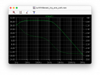
At 20KHz, (no human can hear this) we are down a little ~-1db (bandwidth gain is not great but why we want to improve this general flatness?):

Please see the examples below (increase AC input by 60mV P/p)
Now apply more feedback by reducing 110K resistor to 100K will fix the signal:
My requirements are small.. I need 5-10W to 8 ohm 40Hz-20Khz for my lab bench using only JFET and less than 1% THD.
At 20KHz, (no human can hear this) we are down a little ~-1db (bandwidth gain is not great but why we want to improve this general flatness?):
Last edited:
and why has the simple circuit the gain x4 with one unit? lower source resistor?
But I doubt the LU1014 will do the 2Ampere and also the distortion is not as low as shown from Kokorian in the first circuit.
He claims 0.16% at 1W at 4 Ohm but in Spice I get nearly the double value....
I built this circuit. I added a JFET source follower input buffer here it is working. I found 2 FETS that measure Vgs 1.86v at 12v/.47 ohm source resistor and put them in. Unfortunately, something kills the TOP LU FET if voltage goes past a certain level, with 1 ohm source resistors this voltage is around 21vDC with .47ohm this voltage is around 18.5vDC. I'm all ears on how to stop the top FET from getting destroyed? Should I parallel additional stages?
Video of LU SRPP amp build was too big to post here.
Last edited:
An interesting device. It would be more useful if the voltage rating was ~90V. It's not a good idea to depend on device matching for biasing the totem pole. And buffering a FET gate is not very useful. You need more OLG. A better amp would use a variety of devices. I don't have great solutions, but this is some suggestions:
Attachments

Around Vgs = 20V is usually the gate breakdown.Unfortunately, something kills the TOP LU FET if voltage goes past a certain level, with 1 ohm source resistors this voltage is around 21vDC with .47ohm this voltage is around 18.5vDC. I'm all ears on how to stop the top FET from getting destroyed?
Rayma - I can't see how its possible and trying to understand better what is breaking it -- on the source of the upper FET there is 1/2 VCC held in respect to ground; even if the drain voltage is 22vDC, 11vDC or so would be seen at the source of the upper fet. Changing the FETS out several times also shows that the bottom device is undamaged. I am slowly looking at going towards Nelsons suggestion to cascode with IRP240 but wanted to understand the fault mode i'm observing a little better first.
Agreed, it's always better to understand what's happening.
It would help everyone to post the exact circuit, voltages, and component values.
But, exactly how does the top device fail? Shorted gate, open gate, shorted GS, or shorted GD?
It would help everyone to post the exact circuit, voltages, and component values.
But, exactly how does the top device fail? Shorted gate, open gate, shorted GS, or shorted GD?
for some reason I cannot reply or quote you but sorry if I was not clear enough; here is what I am working with:
I am not sure how the top fails. Whatever happens to it causes the waveform to become noisey, draws more current at lower voltages and have much less output swing. I will try to take some measurements of the blown ones.

I am not sure how the top fails. Whatever happens to it causes the waveform to become noisey, draws more current at lower voltages and have much less output swing. I will try to take some measurements of the blown ones.
I haven't yet found anything OTHER than cascodes to be successful for making a stable amplifier with them. And, I tried some weird stuff. 🙂What worked for me was cascoding the LU1014.
It is no problem get it stable if I don't run the top drain voltage past 18vDC or so. It ran for many hours on 15v for instance which of course is not saying a lot for long term stability.
Fet gate leakage gets worse with higher Vds and junction temperature.
It is no problem get it stable if I don't run the top drain voltage past 18vDC or so. It ran for many hours on 15v for instance which of course is not saying a lot for long term stability.
So a 20V power supply voltage causes it to fail?
The output coupling capacitor is 22,000uF, try 1000uF instead and see if it still fails.
As I mentioned, if source resistors are 1 ohm instead of .47 it seems I can ramp up voltage to 20v or so before failure, if they are .47 it takes around 18v to fail. o/p cap on my deadbug circuit is 10,000uf. The power isn't being cycled at the time of failure, its a gradual, slow increase and temperature on the heatsinks at this point is around 30 degrees C.
If it does not fail upon turn-on, then the DC voltages may be changing gradually
and eventually damaging the gate. Hook up DVMs and monitor the Vgs voltages
of each device as it runs. But for the first trial, reduce the coupling capacitor to
say 100uF instead of 10,000uF. If this seems robust, go back to 10,000uF.
I agree that changing to the mu/2 circuit should work also, since the output C
will not be connected directly to the upper source.
Let's see, running about 4 amps at 12V Vds or so? You're right at the line.
Maybe they are running too hot – almost 40W for a package that is designed for decawatt use.
After failure – did Drain become open circuit?
BTW VGS breakdown is in the 12 to 14V range (in DS).
EDIT: Exactly, as Nelson said ^ it is tiny device (we posted at the same time).
After failure – did Drain become open circuit?
BTW VGS breakdown is in the 12 to 14V range (in DS).
EDIT: Exactly, as Nelson said ^ it is tiny device (we posted at the same time).
Last edited:
- Home
- Amplifiers
- Pass Labs
- Using LU1014D in parallel for a power amp stage.