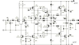
According circuits and inside images of Naim Audio's NAP250 the main difference to NAP160 and NAP110 is an additional discrete power voltage regulator between rectifier and main capacitors - go to schematics under
https://www.diyaudio.com/community/threads/naim-nap250-original-clone-build-thread.390504/page-2
and the attachments.
If I remember correctly, all three models use the same power amplifier board (also with the same circuit), and the power supplies exists in the following versions:
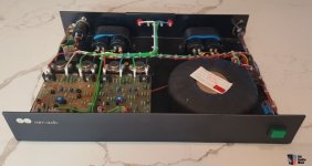
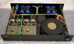
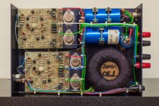
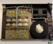
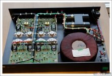
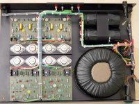
1) NAP250: single winding on toroidal transformer and two main capacitors for both channels but two voltage regulators for each channel
2) NAP160: single winding on toroidal transformer and two main capacitors for each channel (four pcs. at whole) but no voltage regulators (thus less output power than NAP250)
3) NAP110: single winding on (smaller) toroidal transformer and two main capacitors for both channels - also no voltage regulators (therefore even less output power than NAP250)
For my ears NAP160 (and even NAP110 at low listening levels) sounds better in most respects - probably because of the small (only 10uF) elcaps at the output of (i. e. behind) the discrete serial (not shunt) voltage regulators, it's sonic signature probably affects the overall sound character.
Maybe also due to the fact that the NAP250 (compared to the NAP160) has no separate transformer secundary windings for each channel and therefore the GND management is (and must be) carried out total differently.
To find out this exactly I want to use large elcaps (10mF resp. 10.000uF/63V) also at the output of the voltage regulators of NAP250 (i. e. replace of the small present 10uF caps between voltage regulator and power amp voltage input).
To check this without risk of destroy of the voltage regulator modules additional protect steps (like inrush current limiter for charging while switch-on/diode for discharge after switch-off this caps) are absolutely necessary.
Who had already perform this and which impressions while a listening test were after doing this perceived ?
Please note - everything mentioned above refers to the model series described at the beginning of the 80s (maybe predecessors of olive series) - go to
https://www.avoptions.com/downloads/manuals/Naim-Audio-Brochure-1981.pdf
Even this series I know in different versions:
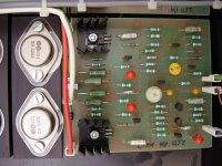
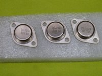
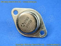
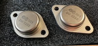
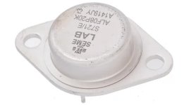
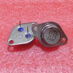
1) with NPN output power devices from Semelab NA001 "SM3282" (are there a datasheet from Semelab ? - I had only make listening tests with this version, bought in 1981)
2) with NPN output power devices from Semelab "SM8927" (have never heard)
both probably identical to Semelab's BDY58 - go to the attached datasheet
but I don't know exactly.
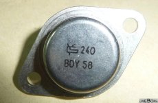
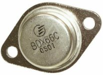
3) with NPN output power devices from Thomson CSF (later SGS resp. ST) "BDY58" (also have never heard)
some additional URL's:
http://www.acoustica.org.uk/t/naim/power_amps.html
https://www.stereophile.com/content/naim-nac-62-preamplifier-nap-140-power-amplifier
https://www.hificritic.com/uploads/2/8/8/0/28808909/_excerpt-201603-3.pdf
https://m.review33.com/forum_msg.php?db=1&topic=79051010190053&start=190&sort=
https://community.naimaudio.com/t/what-type-of-transistor-is-the-na009/10119?page=3
https://www.diyaudio.com/community/threads/naim-nap-110-amp-high-dc-offset-and-mute-channel.257524/
https://pinkfishmedia.net/forum/threads/faulty-nap-110-help-me-please.150581/
http://art-and-technology.blogspot.com/2016/05/the-naim-audio-game.html
https://www.diyaudio.com/community/threads/nap250-amp-boards-regulator-boards.344855/
https://www.diyaudio.com/community/threads/naim-rebuild-boards-nap-140-and-nac.387889/
https://www.diyaudio.com/community/threads/naim-audio-power-amp-grounding-question.172367/
https://www.stereonet.com/forums/topic/93048-dusty-old-naim-gear-options-for-a-friend/
P.S.: are there genuine service manuals published from that time ?
https://www.diyaudio.com/community/threads/naim-nap250-original-clone-build-thread.390504/page-2
and the attachments.
If I remember correctly, all three models use the same power amplifier board (also with the same circuit), and the power supplies exists in the following versions:
1) NAP250: single winding on toroidal transformer and two main capacitors for both channels but two voltage regulators for each channel
2) NAP160: single winding on toroidal transformer and two main capacitors for each channel (four pcs. at whole) but no voltage regulators (thus less output power than NAP250)
3) NAP110: single winding on (smaller) toroidal transformer and two main capacitors for both channels - also no voltage regulators (therefore even less output power than NAP250)
For my ears NAP160 (and even NAP110 at low listening levels) sounds better in most respects - probably because of the small (only 10uF) elcaps at the output of (i. e. behind) the discrete serial (not shunt) voltage regulators, it's sonic signature probably affects the overall sound character.
Maybe also due to the fact that the NAP250 (compared to the NAP160) has no separate transformer secundary windings for each channel and therefore the GND management is (and must be) carried out total differently.
To find out this exactly I want to use large elcaps (10mF resp. 10.000uF/63V) also at the output of the voltage regulators of NAP250 (i. e. replace of the small present 10uF caps between voltage regulator and power amp voltage input).
To check this without risk of destroy of the voltage regulator modules additional protect steps (like inrush current limiter for charging while switch-on/diode for discharge after switch-off this caps) are absolutely necessary.
Who had already perform this and which impressions while a listening test were after doing this perceived ?
Please note - everything mentioned above refers to the model series described at the beginning of the 80s (maybe predecessors of olive series) - go to
https://www.avoptions.com/downloads/manuals/Naim-Audio-Brochure-1981.pdf
Even this series I know in different versions:
1) with NPN output power devices from Semelab NA001 "SM3282" (are there a datasheet from Semelab ? - I had only make listening tests with this version, bought in 1981)
2) with NPN output power devices from Semelab "SM8927" (have never heard)
both probably identical to Semelab's BDY58 - go to the attached datasheet
but I don't know exactly.
3) with NPN output power devices from Thomson CSF (later SGS resp. ST) "BDY58" (also have never heard)
some additional URL's:
http://www.acoustica.org.uk/t/naim/power_amps.html
https://www.stereophile.com/content/naim-nac-62-preamplifier-nap-140-power-amplifier
https://www.hificritic.com/uploads/2/8/8/0/28808909/_excerpt-201603-3.pdf
https://m.review33.com/forum_msg.php?db=1&topic=79051010190053&start=190&sort=
https://community.naimaudio.com/t/what-type-of-transistor-is-the-na009/10119?page=3
https://www.diyaudio.com/community/threads/naim-nap-110-amp-high-dc-offset-and-mute-channel.257524/
https://pinkfishmedia.net/forum/threads/faulty-nap-110-help-me-please.150581/
http://art-and-technology.blogspot.com/2016/05/the-naim-audio-game.html
https://www.diyaudio.com/community/threads/nap250-amp-boards-regulator-boards.344855/
https://www.diyaudio.com/community/threads/naim-rebuild-boards-nap-140-and-nac.387889/
https://www.diyaudio.com/community/threads/naim-audio-power-amp-grounding-question.172367/
https://www.stereonet.com/forums/topic/93048-dusty-old-naim-gear-options-for-a-friend/
P.S.: are there genuine service manuals published from that time ?
Attachments
-
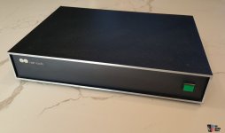 NAP160-250-front.jpg62.1 KB · Views: 446
 -
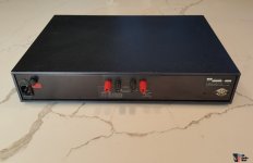 NAP160-250-rear.jpg64.4 KB · Views: 379
 -
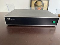 NAP160-250-frontII.jpg70.5 KB · Views: 447
 -
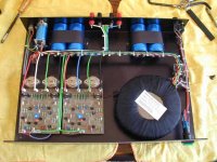 Nap160.jpg29.3 KB · Views: 549
 -
 NAP160-I.jpg75.7 KB · Views: 495
 -
 NAP160-II.jpg101.3 KB · Views: 514
 -
 NAP160-250 PA-module-SM8927.jpg483.8 KB · Views: 574
 -
 NAP160-250 PA-module-SM3282.jpg334.6 KB · Views: 434
 -
 NAP110 BDY56 CSF.jpg677.1 KB · Views: 516
 -
 NAP250-II.jpg106.8 KB · Views: 566
 -
 NAP250-I.jpg80 KB · Views: 506
 -
 NAP250-III.jpg321 KB · Views: 633
 -
BDY55-56-57-58 THOMSON-CSF 1981 databook.pdf2 MB · Views: 208
-
 NAP160-250 schematic-II.jpg86.6 KB · Views: 614
 -
NAP250 voltage reg.pdf43.8 KB · Views: 203
-
NAP160-250-schematic.pdf69.1 KB · Views: 196
-
BDY58-SemeLAB.pdf19.1 KB · Views: 166
-
 The Original and still the best.jpeg193.1 KB · Views: 581
 -
 The Original and still the best-II.jpeg342.9 KB · Views: 517
 -
 The Original and still the best-III.jpeg389 KB · Views: 450
supplement of images - BDY58 versions, various SEMELAB logos and brochure 1981.
Attachments
-
 BDY58 CSF-II.jpg33 KB · Views: 147
 -
 BDY58 CSF.jpg57.6 KB · Views: 134
 -
 BDY58 Thomson.jpg104 KB · Views: 141
 -
 Semelab SM3282 (Naim Audio).jpg418.5 KB · Views: 148
 -
 Semelab-logo-I.jpg30.2 KB · Views: 134
 -
 Semelab-logo-II.jpg20.6 KB · Views: 128
 -
 Semelab-logo III.jpg44.9 KB · Views: 138
 -
 Semelab-logo-V.jpg208.6 KB · Views: 131
 -
 Semelab-logo-IV.jpg44.3 KB · Views: 154
 -
Naim-Audio-Brochure-1981-I.pdf947.5 KB · Views: 152
-
Naim-Audio-Brochure-1981-II.pdf962.2 KB · Views: 165
-
Naim-Audio-Brochure-1981-III.pdf696.8 KB · Views: 143
Last edited:
Larger regulator output capacitors will slow the transient response of the regulators.
The 10uF is likely the minimum size required to ensure regulator stability.
The 10uF is likely the minimum size required to ensure regulator stability.
Your premise seems to be that the regulators are inferior to big caps. Ok.
The 250 and 110 will sound different for reasons other than psu. Obviously, the power transistors are different. The parts matching may be different too, the size of the transformer. How much of the difference is due to the regulators?
I don't quite get the idea of using 10mF caps on the 250 regulator outputs. The regulators are intended to provide low impedance at low frequencies so that only 10uF caps are needed. A 10mF cap is a much physically larger component and so it will have much higher inductance, negating the effect of the increased capacitance at high frequencies. The 10mF will also reduce the open loop gain of the regulators and will modify their closed loop stability. So you will not end up just listening to the 10mF caps but rather a sort of Franken-regulator, lol.
I suppose it would be better to swap the regualtors out entirely and replace with 10mF caps, except that the voltage will be wrong. Tricky.

I can’t speak to modern NAIMs, but i owned 2 x NAIM 160, the 250 was pretty much the same but for the regs. The NAIM 250 substantially outperformed 160 particularily when driving somethign very hard (ie single or syacked Dayon Wright XG8 ESLs). Of the many amps we tried it was by far the best driving such a load.
dave
dave
;-)
The 110 has the best performance.
Test: connect channel-separate parts like the 2 x 2 (to disoriented: connect + and +, - and -) caps of the 160. Or connect the outputs of the 2 x 2 (to disoriented: connect + and +, - and -) regulators of the 250.
The 110 has the best performance.
Test: connect channel-separate parts like the 2 x 2 (to disoriented: connect + and +, - and -) caps of the 160. Or connect the outputs of the 2 x 2 (to disoriented: connect + and +, - and -) regulators of the 250.
this is from my view the reason, why the transient response of each regulator affects the sonic character of each power amp stages much more than aLarger regulator output capacitors will slow the transient response of the regulators.
The 10uF is likely the minimum size required to ensure regulator stability.
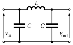
simple π (Pi) filter behind rectifier consist of two low ESR capacitors (e.g. 22000uF) and a air coil between 5 and 10 mH with resistance between 0,3-0,6 Ω - as long as the right main transformer is in use.
Check out TAA article "A Family of Power Amplifier regulated Power Supplies" - go therefore to attachment in post #16 under
https://www.diyaudio.com/community/threads/linear-voltage-regulators-for-power-amps.387946/
in post 51-57 under
https://www.diyaudio.com/community/threads/tweaking-classic-linn-lk1-lk2-lk280.106226/page-3
you will find the schematics of Linn's power amp models LK-2, LK-280 and Klout - all this models use also voltage regulators similar to those from NAP250
Attachments
How do you define better sound? Do regulators always make the sound better, even in the presumably simpler example of a preamp?
Lots of conflicting opinions there. I think it is a question of comparing one set of sonic attributes vs another.
Lots of conflicting opinions there. I think it is a question of comparing one set of sonic attributes vs another.
It's often assumed that regulators always improve sound quality when they reduce noise and maintain a steadier voltage.
This is a reasonable assumption.
It is not always true! Sometimes regulators do more harm than good. They have more complex behaviour than capacitors. It's hard to beat good quality capacitors (from a sound quality perspective).
This is a reasonable assumption.
It is not always true! Sometimes regulators do more harm than good. They have more complex behaviour than capacitors. It's hard to beat good quality capacitors (from a sound quality perspective).
It's often assumed that regulators always improve sound quality when they reduce noise and maintain a steadier voltage.
This is a reasonable assumption.
It is not always true!
Execution is always important.
dave
Fact is, any decent regulated PS will measure better than plain CRC or CLC, but as definition of good sound for some requires high harmonic distortion or ‘soft’ bass or something entirely else, we can never get unanimous agreement what is ‘better’.
For me personally, there is no good enough amplifier without regulated PS. It does not change amplifier distortion or frequency response, but it improves a lot soundstage and fine sound details.
Transient response is, IMO, most important property of voltage regulator. If regulator output voltage variation is in the single digit mV range for any ridiculously high load change at highest possible dI/dt for an audio signal and remains in uV range for amplifier output in 1-10 W output power range, then that is for all purposes ideal voltage source that enables any audio amplifier to work to maximum extent of its design. There in no discussion possible about ‘sound of PS’ like it is with ordinary supplies. Such PS is completely transparent.
Well, I think we have to be very careful when we prioritize an electrical measurement over the perception of a seasoned listener. In my experience, this is always folly.
It's not a scientific approach and can cause the righteous designer to get stuck in a rut.
Just sayin'.
It's not a scientific approach and can cause the righteous designer to get stuck in a rut.
Just sayin'.
No arguments here. It also usually improves bass delineation. Other aspects, like natural tonality, decay and dynamics, often suffer. Ime this stands true with both power amps and preamps, ss and tube, series or shunt regulators. Some regulators certainly offer a more acceptable set of qualities than others, but in the end there is always a compromise to be accepted or not.it improves a lot soundstage
Since our hearing perceives even the differences of the same components as "unclean, bumpy, hanging, tearing", there remains probably only one power supply, more precisely: one voltage for (almost) all matters to be done to hear music cleanly, clearly, dynamically;-)
... although: quite a few do not need clean-sounding electronic components for their unclean, bumpy, catchy, tearing, flat-sounding speakers)-;
... although: quite a few do not need clean-sounding electronic components for their unclean, bumpy, catchy, tearing, flat-sounding speakers)-;
Other aspects, like natural tonality, decay and dynamics, often suffer.
YMMV. Mine mileage is ‘1000 miles/gallon’ with regulated PS. 😉
In example, for months I was evaluating and carefully listening A class amplifier with infinitesimal distortion (even that 0.0000x values are monotonic with H3 20 dB below H2), 1.7 MHz power bandwidth, 100 V/us slew rate, DF of 370/8Ω, total output noise 20 uV and so on, powered by a simple CRC PS. with synchronized rectifiers and good quality capacitors (33 mF CDE380LX). Sound was everything I could wish for.
Then, resistors in the CRC supply were replaced with Jung-Didden variant of super regulator. There was absolutely no degradation of tonality, decay or dynamics. On the contrary.
that's exact my experiences. Unfortunately really good capacitors like those underIt's often assumed that regulators always improve sound quality when they reduce noise and maintain a steadier voltage.
This is a reasonable assumption.
It is not always true! Sometimes regulators do more harm than good. They have more complex behaviour than capacitors. It's hard to beat good quality capacitors (from a sound quality perspective).
https://www.mundorf.com/audio/en/shop/capacitors/power_caps/mlytic_hc/MLytic-HC/?card=2519
in currently available products a no-go (even with brands like Naim Audio) - because the requirement for cost efficiency is not met.
Even for diy projects very expensive.
It would be interesting to know whether it is even possible to design a high power voltage regulator for Class AB power amplifiers with inexpensive electrolytic capacitors of the same sonic quality like two expensive capacitors together with a choke as air coil.
To find very well sounding transistors will be expensive. 9 out of 10 sound cloudy, flat, gray, grainy, slowed down, cloudy or otherwise: nothing for PSUs either.
And: the more complex the regulator circuits, the worse they sound.
In addition, most already fail when it comes to the sensible placement of the speakers)-;
And: the more complex the regulator circuits, the worse they sound.
In addition, most already fail when it comes to the sensible placement of the speakers)-;
Mundorf's are yummy.It would be interesting to know whether it is even possible to design a high power voltage regulator for Class AB power amplifiers with inexpensive electrolytic capacitors of the same sonic quality like two expensive capacitors together with a choke as air coil.
The limitation even of a perfect cap would still be rising impedance towards dc. Some amp designs don't react well to this. But if that is not an issue, I think it's a tough challenge.
I decided to do both: regulator upstream to control the near dc impedance and caps downstream to control the hf. Also allows me to locate the noisy part of the PSU in a separate box.
If regular capacitors are necessary, I always recommend choosing the heaviest ones. More weight, more metal. 😉
Then someone recently invented a deep etched foil technology that produced a massive increase in electrode surface area with less metal. How does this stack up with the assumption that we can still predict to some degree, the capacitor's performance by its weight?
- Home
- Amplifiers
- Solid State
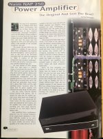
- Really better Sound through use of additional Voltage Regulator in NAIM Audio's Chrome Bumper Power Amp NAP250 (compared with NAP160/NAP110)?