In master mode Fs will be limited to a maximum of MCLK_I/256 44.1 kHz. Slave mode will get you to roughly 81kHz.
I guess my AD1896 experiment will use this ASRC as a "pass-thru" device. That is, the I2S signal (from Amanero) will pass thru the AD1896 (unchanged; but not by using the AD1896 "BYPASS" feature). The AD1896 can increase the word length up to 24 bit (using dithering), but the TDA1305 I plan on using with it can only handle 20 bit. So I'll take it up to that.In master mode Fs will be limited to a maximum of MCLK_I/256 44.1 kHz. Slave mode will get you to roughly 81kHz.
The TDA1305 can handle a max of 96k, but not via I2S. So 44.1 k/ 20 bit it shall be.
Still stuck with the AD1896's weird SDATA_OUT issue. See my prev post.
I did test AD1896, feeding a TDA1305.Still stuck with the AD1896's weird SDATA_OUT issue.
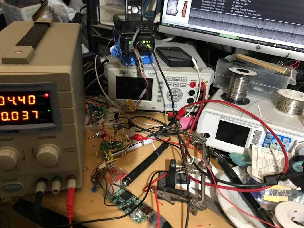
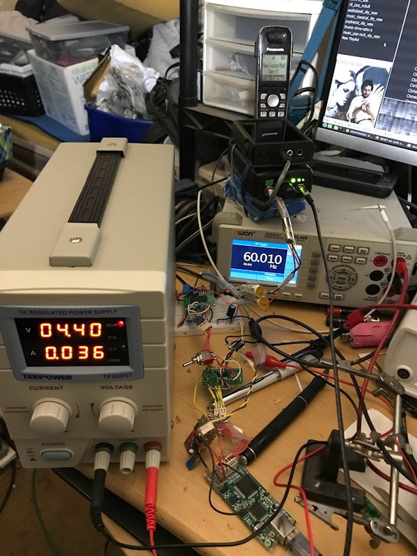
Got noise. I don't have noise issue if I just feed the Amanero (via /2) to TDA1305 (clean, clear music! Even with the typical messy setup depicted in my photos)
I wonder if the MCLK_I = 11.289 MHz is too low for the AD1896? (I do have to /2 the MCK: from 22.5xx to 11.289 because the tda1305 can handle only up to 18.xxx MHz max).
Page 22 AD1896 datasheet: "The master clock has to be at least 138 times greater than the maximum input or output sample rate." Do you meet that?
You could apply the undivided clock to the ASRC and the divided clock to the DAC. Are the logic high levels as expected by the receiving chip?
You could apply the undivided clock to the ASRC and the divided clock to the DAC. Are the logic high levels as expected by the receiving chip?
At least if it fits with the clock requirements of both chips. If I understand it correctly, a TDA1305 in I2S mode requires either 256 times the sample rate (single speed mode) or 128 times the sample rate (double speed mode) as system clock. I think an AD1896 with 22.something MHz master clock set to output data in I2S format, master mode, sample rate = master clock frequency/256 should be able to drive a TDA1305 in double speed mode with a system clock of 11.something MHz.
I'll have to try the double-speed mode engaged.
In single-speed mode, I fed the MCK of AD1836 a 22.579 Mhz MCK (from Amanero) ; but fed MCK of TDA1305 11.289 ( /2 from same Amanero MCK), but no audio from TDA1305.
Okay, let's forget about the AD1896 for a moment ...
The TDA1305 fed directly from the Amanero (but MCK /2 of course) seems to work fine.... BUT... on further, careful listen and use, I noted serious issues with the TDA1305 audio output -- say, if I take the volume of my driven headphone amp up past 9 o'ckock : it distorts heavily and massive on/off thumps. I suspected DC offset and indeed that's what found: about 2.5 Vdc . In the TDA1305 datasheet (p 14), an output is suggested with no output caps. Just 1nF from VOL or VOR to FILTCL or FILTCR. Indeed the TDA1305 datasheet notes ...
The aforementioned Chinese 1305 kit uses 20UF electros on the outputs:
https://www.diyaudio.com/community/...-3-5-cd-player-schematics.395185/post-7255753
In single-speed mode, I fed the MCK of AD1836 a 22.579 Mhz MCK (from Amanero) ; but fed MCK of TDA1305 11.289 ( /2 from same Amanero MCK), but no audio from TDA1305.
Okay, let's forget about the AD1896 for a moment ...
The TDA1305 fed directly from the Amanero (but MCK /2 of course) seems to work fine.... BUT... on further, careful listen and use, I noted serious issues with the TDA1305 audio output -- say, if I take the volume of my driven headphone amp up past 9 o'ckock : it distorts heavily and massive on/off thumps. I suspected DC offset and indeed that's what found: about 2.5 Vdc . In the TDA1305 datasheet (p 14), an output is suggested with no output caps. Just 1nF from VOL or VOR to FILTCL or FILTCR. Indeed the TDA1305 datasheet notes ...
Must be a datasheet mistake given the large DC offset I noted. Or does Philips know something we don't?[datasheet, P16] A typical application diagram is illustrated in Fig.5 [p. 15] . The left and right channel outputs can drive a line output directly.
The aforementioned Chinese 1305 kit uses 20UF electros on the outputs:
https://www.diyaudio.com/community/...-3-5-cd-player-schematics.395185/post-7255753
Looks like a silly oversight in the application diagram. The DAC has a single analogue supply, so it's logical that its output is biased somewhere halfway supply and ground, but they should have drawn an AC coupling capacitor per channel.

I got off lucky in that I didn't damage my tiny headphone amp -- which I built w/o any any input or output coupling caps or servo protection. I like pure fidelity so mostly ditch protection.Looks like a silly oversight in the application diagram. The DAC has a single analogue supply, so it's logical that its output is biased somewhere halfway supply and ground, but they should have drawn an AC coupling capacitor per channel.
Anyone: Suggest a good clean output solution for the TDA1305. I have some decent 10 uF Sprague films that I often use as DC blockers. Maybe something else?
You can only go so far as that ORACLE masquerade, dude 😉The datasheet doesn't spoon-feed. You are expected to bring something to the party.
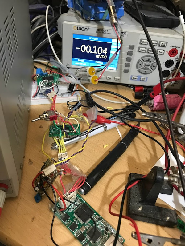
In any case ... experimenting with the output and DC blocking, it seems that a low-value R is more important than just a cap. I played with JUST caps (10 uF film to 220uF electro BlacGate) and reduced DC by only 0.8Vdc for BOTH those caps (still: 1.7vdc out) . But simply adding a 10R in series brought DC output to 0.4mVdc.
Yeah ... those Chinese know what they are doing!
https://www.diyaudio.com/community/...-3-5-cd-player-schematics.395185/post-7255753
I got off lucky in that I didn't damage my tiny headphone amp -- which I built w/o any any input or output coupling caps or servo protection. I like pure fidelity so mostly ditch protection.
Anyone: Suggest a good clean output solution for the TDA1305. I have some decent 10 uF Sprague films that I often use as DC blockers. Maybe something else?
If you should want to keep it DC coupled:
Difference amplifier amplifying the difference between the output and the 2.5 V reference, making sure to buffer the reference because injecting signal current into it would be a bad idea. You have to include something to trim away the last 65 mV +/- 15 mV.
Using a symmetrical +/- 2.5 V analogue supply, connecting analogue and digital grounds to -2.5 V, shifting down the digital supply by 2.5 V and level shifting of the digital input signals. Sounds rather awkward.
Last edited:
Just using two 10 ohm ERO brand metal-film 1/4w in series (total =20R), followed by a 10 uF Sprague. Loaded, the output DC is very low (0.27 milliVdc).
And sonics have improved quite bit; no doubt because input of amp is no longer struggling.
Hmmm ... not to far now from that decent-sounding Chinese tda1305 kit topology, but with added very strong bonus of just a high-quality Amanero feeding the 1305 directly.
Still working on the AD1896 issue, which I might abandon if double-speed does not work.
Indeed, and: Smarty-pants know-it-alls never rise and repeat in a cosmos only 14BN years red-shifted.There is nothing sage-like in pointing out the bleeding obvious.
===============
The AD1896 is now working at double-speed (Prev. at single speed.; pin 20) on a TDA1305 and Amanero on either side. Thx for the tip MarcelvdG!
Wow -- lots of work. Was it worth it?
Listening carefully, and comparing my notes to w/ and w/o AD1896 ... yes, a definite step up. And this is with the un-optimized setup shown in the photos. With clean PSU regs, feeding ICs independently, and also separate analog and digital Vcc pins, there are gains to be had for sure.
Not sure a 1305 has been up-sampled before. Yes, it's possible and with good results at low cost, and small footprint. Low power consumption, too.
Time was when this stuff had a barrier to entry. These days any muppet with net access can download something beyond their comprehension and then moan when it all goes wrong. However we are where we are.
FWIW, the AD1896 is a sample rate converter not an oversampler.
FWIW, the AD1896 is a sample rate converter not an oversampler.
Yes and no. See DS, p. 18FWIW, the AD1896 is a sample rate converter not an oversampler.
https://www.analog.com/media/en/technical-documentation/data-sheets/ad1896.pdf
- Home
- Source & Line
- Digital Line Level
- RESET pin (with overbar)