Yeah, I was on that from the get-go. It has always been I2S config. Pg 22 of datasheet. The various SMODE pins. For both out and in. Double checked them on both protoboards. They are I2S in and out, wired correctly.What is the serial audio source ?
About that
Serial Data Port Master Clock Modes;
Table IV. Serial Data Port Clock Modes
AD1896 datasheet PDF pg. 24
"MMODE"
I tried these two combos:
Both serial ports are in slave mode.
and
Input serial port is master with 256 x f S_IN .
And still no I2S output.
The 3-pin MMODE config has six more possible combos. Not sure any are worth pursuing.
In what mode is whatever drives the input and whatever loads the output?
The most usual mode is slave for any I2S input and master for any I2S output.
If you use the output in slave mode, there must be something else generating word and bit clocks and applying those to the output I2S interface. Is there such a thing in your circuit?
If you use the input in master mode, whatever drives the I2S input has to accept the bit and word clocks that the ASRC generates. Does it?
Last edited:
I engaged pin 9, BYPASS, "ASRC Bypass Mode, Active High", which should send the three input lines directly to three output lines, BYPASSING the ASRC completely. But I still get nothing on any output pin.
Last edited:
I don't see any note that BYPASS changes the I2S modes, so if those modes are set wrong, it won't work in bypass either.
Normally you would have to set the output to master mode.
Normally you would have to set the output to master mode.

YOU ASKED FOR IT ... and the ball is in your court....A diagram of your setup might help.

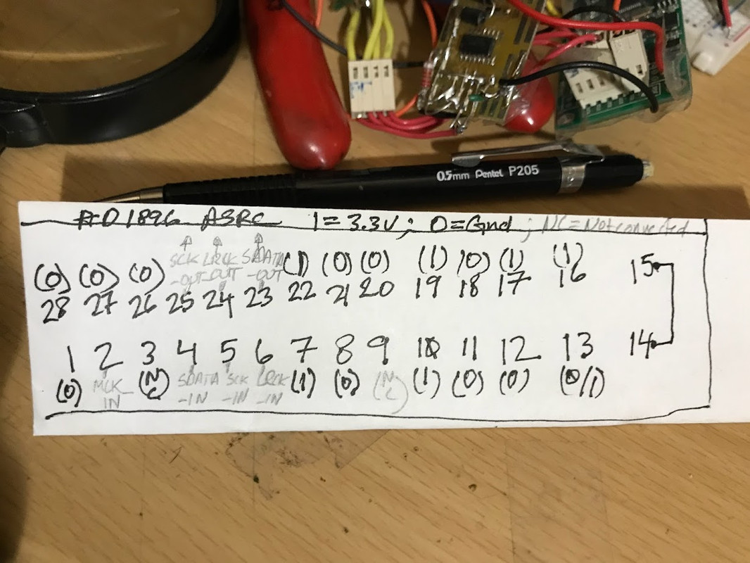
It looks messy but all connections are solid and double or triple checked with DMM and o'scope.
Built the AD1896 on green proto board 2x (each AD 1896 IC came from two separate sources: Digikey/Mouser -- same confusing results).
The 3.3v power for the AD1896 is coming from USB-I2S board via std. gpio power and gnd taps.
The two-way switch is for RESET (toggles between 0 and 1).
The small yellow board is /2. Everything before AD1896 works fine as it has been used in other projects such as recent TDA1305 and several others.
Actually what he asked for was a diagram. Not a picture of a rat's nest. So the ball is still in your court. 😉YOU ASKED FOR IT ... and the ball is in your court....
Seriously, dude. Draw a schematic. It's not hard and it would clarify so many things. Maybe you'll even find the reason why your circuit is misbehaving.
Tom
MMode [0:2] is set to 000. Both serial ports are in slave mode. Where are the clock signals required to drive the output ?
FWIW, there is a SRC4192/PCM1792 design in the forum. To borrow from all good textbooks, finding it is left as an exercise to the reader.
As noted previously, I tried MMode [0:2] set to 111. Didn't work. Not sure what you mean about "clock signals required to drive the output". MCLK_IN (pin 2) = 11.289Mhz clk coming in from USB-I2S board. BCK_IN = 2.8MHz and LRCK_IN = 44.1khzMMode [0:2] is set to 000. Both serial ports are in slave mode. Where are the clock signals required to drive the output ?
Last edited:
The datasheet p. 24 Table IV (and paragraph) is a bit vague on pin set up. Your diagram seems to suggest "011 Output serial port is master with 256 x fS_OUT." Is what I'm after.Same information in a block diagram.
I don't have a load (DAC) connected to ASRC -- just bare pins from ASRC which I probe with freq counter or DMM.
Will try it in the next 24 hrs.
Please note that not all DMMs can measure megahertz signals.I probe with freq counter or DMM.
You usually get to see the time average when you do a DC measurement, so you can distinguish between all zeros, all ones and something in between.
Almost home because of MarcelvdG's clarifying artwork! See photos below, with DMM.


Only SDATA_O (I2S, data out), which should fluctuate with music, seems to remains constant (on DMM): 66.147-66.015 kHz This will remain 66.147-66.015 kHz when no music is playing -- a problem!
SDATA_I (I2S, data in) entering the AD1986 from USB-I2S device, when music playing, varies 320.00-380.00 kHz. This will be 0.00hz when no music is playing -- of course.
The outputs are quite sensitive. likely due to messy setup, and simply removing DMM probe forces me to use the RESET toggle (very useful switch).
Might connect it to DAC chip soon!
"There are no problems ... only solutions."The quality of the test tools are the least of his problems.
Last edited:
The MAXIMUM usable sampling rate that a system clock of 11.289 MHz (before oversampling) is 44.1 khz, correct?
That is, if I've only got a 11.289 crystal osc feeding into the ASRC device (MCLK input), I can't upsample to, say, 96 khz (i.e., the LRCK ), correct?
That is, if I've only got a 11.289 crystal osc feeding into the ASRC device (MCLK input), I can't upsample to, say, 96 khz (i.e., the LRCK ), correct?
- Home
- Source & Line
- Digital Line Level
- RESET pin (with overbar)