You will find fast ones, which do sound slow, cloudy, not musical, and you will find slow ones, which sound fast and open and with musical flow.Have you tried different types of diodes? What would be better, faster or slower?
I can only advise: buy 50 different types and try them. The contrastive comparison shows their sound characteristics, which always remain the same at all points and functions of a circuit. And a further result: A repertoire for tonal! tunings, for sound! tunings;-)
They sound as different as beers or wines taste;-)
I also wanted to write about the test of diodes and transistors:
Power diodes and power transistors simply inserts into the power supply. Either instead of the original (1) or, if e.g. transistors do not survive this application, simply in the middle, whether before or after the capacitors or filter coils - no matter (2). Something like seen below.
Use for this purpose a single ended amp or follower with ONE voltage only - so you also have a reference amplifier or follower;-)
Attachments
![DSCN0267[1].JPG](/community/data/attachments/1071/1071525-0ccb8ae146cfaf2d48fa84e7bfc57495.jpg?hash=DMuK4UbPry)
I would try to build half-wave-symmetrical: e.g. 2 diodes (to bias) and the input between. Because the further character of a unsymmetrical part (1 diode) does "distort" the sound , exacter: "noisy" the signal, the sound)-;You need to add a bias (diode) between the bases of the output transistors.
http://rca.vobj.org/RCA Engineer/RCA Engineer v12/RCA Engineer v12n2/p56Fisher-SymmetryPowerAmplifier.pdf
And: I would try to run these circuits without bootstrap. May be, the ears do say: "sounds better than with"-)
Still mentioned afterwards:You will find fast ones, which do sound slow, cloudy, not musical, and you will find slow ones, which sound fast and open and with musical flow.
I can only advise: buy 50 different types and try them. The contrastive comparison shows their sound characteristics, which always remain the same at all points and functions of a circuit. And a further result: A repertoire for tonal! tunings, for sound! tunings;-)
They sound as different as beers or wines taste;-)
I also wanted to write about the test of diodes and transistors:
Power diodes and power transistors simply inserts into the power supply. Either instead of the original (1) or, if e.g. transistors do not survive this application, simply in the middle, whether before or after the capacitors or filter coils - no matter (2). Something like seen below.
Use for this purpose a single ended amp or follower with ONE voltage only - so you also have a reference amplifier or follower;-)
You can do this with negative voltages also. I want to mention, because induced images create reality; see e.g. "Corona"-)
And: among e.g. 50 tested parts, only 5, i.e. 10 %, will be suitable for audio electronics. The rest can be used for e.g. coffee machines or light controls;-)
And: do not believe that the components of a fat big expensive HighEnd dream amplifier have been determined by ear;-)

I hope that at least some engineers work seriously today. Maybe outside the "HighEnd" bubble.And: do not believe that the components of a fat big expensive HighEnd dream amplifier have been determined by ear;-)
;-)
I don't have much to do with push-pull amplifiers or followers, and I do recommend: no complementary transistors - they sound very different: the half-waves sound very different! It sounds as if a room divider was pushed into the sound image;-) Every time! Has NOTHING to do with "High End" or something like that! No matter how expensive;-)
But I scratched my head just now: in order to maintain the half-wave symmetry as much as possible, but not to use diodes or transistors - which almost always sound worse than, for example, good resistors - as bias regulator. Also, small signal should be preserved. This quickly came out: A little half-waves-symmetric-push-pull-complementary-trasistors-follower. Sounds wonderful;-) Most would give away their grandmother for something like this;-)
(The housing is a usual cheapest "China-Karaoke-Amp", HVA-200. Used trafo, rectifier, caps. Original is a quasi-complementary power amplifier with differential preamplifier and something in between, quasi a NAIM, in it. Also sounds like NAIM;-)
Nothing new, just a reference to symmetry and simplicity and fastness.
And tested;-)
Attachments
![DSCN0270[1].JPG](/community/data/attachments/1074/1074161-56e0515c725340e9651f265af775fc34.jpg?hash=VuBRXHJTQO)
![DSCN0272[1].JPG](/community/data/attachments/1074/1074162-0bf916afed73fb7e0700da423e137cce.jpg?hash=C_kWr-1z-3)
![DSCN0273[1].JPG](/community/data/attachments/1074/1074163-8ae5bd2062684802c3a766cc3c125ef2.jpg?hash=iuW9IGJoSA)
Can you provide address where to send grandmother in exchange for component list? 🙂Most would give away their grandmother for something like this;-)
Would like to build that to use as summer amplifier or buffer I suppose it is,,
I see you use single diode in the rectifier, but transistors not yet cut.🤔
The cool summer-follower;-)
Still had a few MJE3055/2955 lying around. Sonically I had noted - compared to one of my favorites TIP41/42: "Tones smaller, a little potted, braked". Cutting the MJE is not worth it;-) Or use even smaller, better ones, like BD441/442.
I did not measure the hFE of the MJE3055/2955. At the moment the resistance of the bias regulator is 20 kOhm, the base regulators about 50 kOhm - are also used to set the offset. Psu: +/- 26 VDC.
As emitter resistors I used the 0.25 Ohm of the HVA-200. < 2 x 20 mV is the voltage drop across the emitter resistors.
I like to use Panasonic KA-A as capacitors. They are some of the best I have heard. They also sound better than any fat, expensive film capacitors - their problem is their size, so they can only be used for a few octaves, if at all.
Power supply can be seen in #17, sketch 3;-)
Do not use unnecessary switchers and volume controls. Omit everything.
Do not be alarmed: Followers appear quietly for the time being.
As time goes by, they seem increasingly louder. Their cleanliness, dynamics, inner tension make you turn down the volume control further and further. At the moment I listen with the headphone output of a laptop. And that is now only at < 1/2. And I know the neighbor is on 180;-)
And now send me your grandmother;-)
Last edited:
Also something practical: how should solder joints in audio electronics look like. Minimal solder (no one would wire their expensive boxes with solder or rods of lead). You must be able to look through the holes of the board. It's about the definition of current, so of signal. There would be more processing details to mention, but heads are not for scratching only;-)
Attachments
![DSCN0280[1].JPG](/community/data/attachments/1077/1077375-1a9453d1e89d83de8a10b7ad9c4791fa.jpg?hash=GpRT0eidg9)
A parable - it seems necessary to me in this social milieu(-:
To make a good beer or wine or brandy, it is not enough to record alcohol content, mineral content, acidity, water content. It does not need a chemist or a chemistry laboratory. It takes a winemaker, brewer, distiller.
To set a super TV picture, it is not enough to watch two or three light frequencies in wave form on a monitor.
To build a super "audio amplifier", it is not enough to look at two or three frequencies on an oscilloscope;-)
Too much complex are these "events" taste, image, sound, others, to be handled with completely undercomplex and also not applicable, supposedly "scientific", "measuring methods";-)-;
... and with audio electronics it ultimately depends on every single screw, every single solder joint, every single snippet of wire;-)
No, that is romantic hogwash. As Californian and Australian winemakers have clearly demonstrated, proper analysis and rational approach show the way, not magic subjective "claimed" expertise. The same applies for amplifier design. Cutting transistors in half or polishing mica insulators do not improve performance, unless one has smoked mushrooms.
![DSCN0289[1].JPG](/community/data/attachments/1081/1081172-bead9caff30f074653bc7fec5d5b5f4f.jpg?hash=vq2cr_MPB0)
![DSCN0302[1].JPG](/community/data/attachments/1082/1082860-a0d2dd500f8ad93326dd1cb27c51275d.jpg?hash=oNLdUA-K2T)
I'm looking at recordings from the Munich High End...-)
Loudspeaker placement:
But how can we determine this relationship?
Put the loudspeakers about 0.5 meters apart at the beginning. And listen. After a while, put them 0.6 meters apart. And listen further. Then move them to 0.7 meters apart. And so on. You'll pretty soon hit a distance where the sound image breaks apart. Most of the time, also somewhat depending on listening distance, room, quality of sources and amplifiers, the distance between speakers will be less than a meter (center - center). With very large speakers (home audio) it will very rarely be over 1.5 meters.
If the sound image is not torn apart, the sound will be spatially deep, full-bodied, with an appropriate relationship of contours and colors, musical, also "processual", i.e. rhythmically correct, homogeneous and without a sweet spot.
Other considerations, such as distance to the rear wall, angulation, placement across the width or length of the room..., I will leave unmentioned here.
Positions at moment here: fullrangespeakers, 5", closed 7 liter box, 0.77 meters (center - center) apart; listening distance 3.5 meters. Heavily angled in.
Or: 2 meter tall line array fullrange dipoles, 2 x 6 x 12" drivers: 1.5 meter distance to each other (center - center) at > 4 meters listening distance. Angled in.
This is an offer to be able to compare different loudspeakers, and hifi systems, sonically at all. Whether someone nevertheless prefers to push his boxes 3 meters apart, in order to get, with poor quality of e.g. speakers, sources, amplifiers, eqipment..., an impression of e.g. "room", be granted him;-)
Note that when replacing equipment and single parts (as transes, resistors, caps, cables), you had to reposition and realign the speakers;-)
Loudspeaker placement:
- Loudspeakers have different size sound images - as well as sources and amplifiers, individual components.
- Mostly we hear only one music (one recording, one disc), which is reproduced on two channels (stereo), with the same signals on both channels, often with only slight deviations in volume and phase: So most of it is "mono".
But how can we determine this relationship?
Put the loudspeakers about 0.5 meters apart at the beginning. And listen. After a while, put them 0.6 meters apart. And listen further. Then move them to 0.7 meters apart. And so on. You'll pretty soon hit a distance where the sound image breaks apart. Most of the time, also somewhat depending on listening distance, room, quality of sources and amplifiers, the distance between speakers will be less than a meter (center - center). With very large speakers (home audio) it will very rarely be over 1.5 meters.
If the sound image is not torn apart, the sound will be spatially deep, full-bodied, with an appropriate relationship of contours and colors, musical, also "processual", i.e. rhythmically correct, homogeneous and without a sweet spot.
Other considerations, such as distance to the rear wall, angulation, placement across the width or length of the room..., I will leave unmentioned here.
Positions at moment here: fullrangespeakers, 5", closed 7 liter box, 0.77 meters (center - center) apart; listening distance 3.5 meters. Heavily angled in.
Or: 2 meter tall line array fullrange dipoles, 2 x 6 x 12" drivers: 1.5 meter distance to each other (center - center) at > 4 meters listening distance. Angled in.
This is an offer to be able to compare different loudspeakers, and hifi systems, sonically at all. Whether someone nevertheless prefers to push his boxes 3 meters apart, in order to get, with poor quality of e.g. speakers, sources, amplifiers, eqipment..., an impression of e.g. "room", be granted him;-)
Note that when replacing equipment and single parts (as transes, resistors, caps, cables), you had to reposition and realign the speakers;-)
Last edited:
If you want to experience great sound, you don't move your speakers (their individual imaging size is limited;-) out of the position described above, but rather move your chair close to the speakers. To, or into, the large sound image. Then a small correction of the angle, angulation of the speakers could be useful.
Why no double mono power supplies:
Agrumentative first:
Balancing of amplifiers serves (also) to "cancel" power supply AC voltages (and also DC voltages;-).
Power supplies generate voltages that audibly modulate the signal.
Nobody would (or should - I know some experts;-) supply his balanced amplifiers with different power supplies;-)
Channel separated power supplies modulate the signal audibly different: an audible channel deviation: uncleanness.
Further conclusion: power supplies should not be different, not only horizontally but also vertically;
even if they are only regulators, their parts modulate the signal audibly differently.
Further conclusion: even half-wave separated, -different power supplies modulate the signal audibly different, because they consist of different, even if "same", parts.
The practical test: connect your channel separated power supplies together. With this test and the following conclusions almost the whole HighEnd discourse can be rolled up. To the disadvantage of component graves and stuff like that;-)
A look into psu practice also in #17 above;-)
Channel separated power supplies modulate the signal audibly different: an audible channel deviation: uncleanness.
Could you translate this into English?
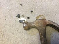
Because power transistors also have a current-misregarding build up - we also hear material, including material tensions, shape, cross-section, mass-stiffness, and more -: here's a little tip to help power transistors sound better: a small cut as seen. At least this one;-)
But there is much more possible;-)
But there is much more possible;-)
Attachments
![DSCN0282[1].JPG](/community/data/attachments/1109/1109649-028a8c6b89a263563730833659b5cfaf.jpg?hash=AoqMa4miY1)
- Home
- Amplifiers
- Solid State
- Cumbbs Koans