I bought a PCB board for tone controls (bass and treble) Baxandall type 12AX7 from China few years ago. Finally now I got back at it again and would like to build a preamp with it.
I am thinking of using the following components:
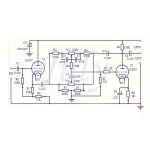
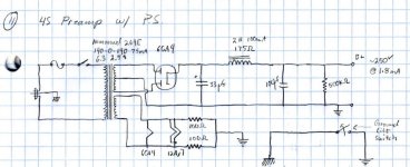
I am taking inspiration for power supply from the attached schematic of the 4S Universal Preamplifier for 12A*7 Tubes, changing the 6CA4 for AZ1, the first 33uf cap for the 8uf oil cap I have.
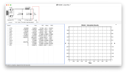
I have simulated the power supply on PSUD2. It's my first time trying to use it. I can't get the graph to populate, nor some voltages on the chart, see attached. I used 200Kohms as T1 resistance. I wasn't sure what to use so I just measured the resistance between the two 117v taps of the transformer. For C1 I used the 0.3r ESR resistance I measured on the 8uf oil cap. For C2 I speculated an ESR resistance of 0.2r. I left R1 the same, thinking is the bleeding resistor.
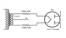
I was thinking of using the 6.3v @ 1.8a tap of the power transformer to power the 4v 1.1a filaments of the AZ1, using 1r 2w resistor on each of the filament to lower the voltage.
What's wrong with my PSUD2 model?
Thanks!
I am thinking of using the following components:
- Baxandall type 12AX7 PCB Board (schematic attached)
- 2x ALPS 100k pots to use for left and right volume
- 2x 500k double gang pots to use for bass and treble
- 1x Sprague 8uf 1kv oil cap as I have many around awaiting to be used
- 1x Orion PR-101 power transformer 250-0-250 @ 60mA, 6.3v @ 0.6A, 6.3v @ 1.8A, bought on ebay, removed from an old reel to reel machine
- 1x AZ1 Mesh plate rectifier, cause they look pretty and I have few around
[*]1x Raytheon 2h 0.062a 170r 450v choke - 1x Hammond chassis with wood frame
I am taking inspiration for power supply from the attached schematic of the 4S Universal Preamplifier for 12A*7 Tubes, changing the 6CA4 for AZ1, the first 33uf cap for the 8uf oil cap I have.
I have simulated the power supply on PSUD2. It's my first time trying to use it. I can't get the graph to populate, nor some voltages on the chart, see attached. I used 200Kohms as T1 resistance. I wasn't sure what to use so I just measured the resistance between the two 117v taps of the transformer. For C1 I used the 0.3r ESR resistance I measured on the 8uf oil cap. For C2 I speculated an ESR resistance of 0.2r. I left R1 the same, thinking is the bleeding resistor.
I was thinking of using the 6.3v @ 1.8a tap of the power transformer to power the 4v 1.1a filaments of the AZ1, using 1r 2w resistor on each of the filament to lower the voltage.
What's wrong with my PSUD2 model?
Thanks!
Attachments

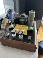
By the way, those two small green boards on the side are 10pc magic eye VU meter indicator tube PCB for EM80 6E2 EM87 EM81 EM84 6E5C. I'm thinking of leaving enough space to try incorporate them.
I looked at that circuit from a previous thread here, looking for a more refined tone stack for an old amplifier I am updating. I modelled it in ltspice and it looked like it would lack a bit of gain for my application. What line level in and out are you looking for?
What will it be driving? You might need a cathode follower on the output as well.
What will it be driving? You might need a cathode follower on the output as well.
I took 200Kohms as T1 resistance. I wasn't sure what to use so I just measured the resistance between the two 117v taps of the transformer.
I don't speak PSUD2, but if the T1 resistance is the secondary winding resistance, then your value must be about a factor 1000 or so too high.
It will be driving one of the various power amplifiers I'm using at the moment. One is a McIntosh MC240 (Push Pull 6L6GC), another is a Decware Zen Triode copy (EL84 single ended).I looked at that circuit from a previous thread here, looking for a more refined tone stack for an old amplifier I am updating. I modelled it in ltspice and it looked like it would lack a bit of gain for my application. What line level in and out are you looking for?
What will it be driving? You might need a cathode follower on the output as well.
I need it because:
- as I play straight from an iMac into the McIntosh MC240 + B&W 801 the volume on some youtube videos is too low at the max volume, so I need a bit of a boost
- on my other setup (Altec A7 + Decware Zen Triode) I would like the boost a bit the bass sometimes
I've never built a preamp so I am planning to start from this PCB board first and see if it helps with the two needs above.
Then would like to build a second one in the future, point to point this time, and use some preamp globe tubes, possibly mesh, for fun and the look of it.
Yes the source impedance is incorrect. To establish the correct value right click on the transformer; then left click the three dots adjacent to "source resistance." That brings up the screen to enter the appropriate values.

R7, first stage bias resistor is too large. You'll want something more like 1K0 to 1K5. Usually R2 and R3 are equal. Also this board will have slightly less than unity gain. For some gain you could make the first stage an anode follower.
All good fortune,
Chris
All good fortune,
Chris
Seems to work now. This is what I got. V(R1) has a max of 95.816. Does it mean with this power supply I would expect a voltage of 95v at R1?

5K Ohm at your desired 250VDC draws 50mA, but your circuit looks more like 5mA or less total.
All good fortune,
Chris
All good fortune,
Chris
To be honest I wasn't too sure what R1 was. I thought it was a bleeding resistor. I see in the schematic of the PCB board I'm using an R1 resistor of 100k already. So I changed in PSUD the value of R1 from 1k to 100k and now I'm getting a value V(R1) of 175v.

The R1 on the circuit board is a different R1 from the PSUD estimated load. By chance, 100K is a reasonable estimate for your circuit's load, so keep it. Someone please correct me, but I think PSUD wants you to spec the transformer secondary as 500VRMS. Looks like it, anyway.
All good fortune,
Chris
All good fortune,
Chris
Last edited:
Due to the high output impedance of the 12AX7 with a 100K Anode load, it is generally recommended to follow it with either a source follower (FET) or Cathode Follower (Tube) buffer to prevent excessively loading the 12AX7 and producing unnecessary levels of distortion.
That arrangement requires three triodes instead of only two. The feedback offered by the tone control network works to reduce output impedance. Of course there is more feedback (and therefore lower Zout) at flat setting than full boost. But still significantly lower than the 40k typical open loop.
If the transformer primary (or secondary) really measures 200K there is something seriously wrong with it. Should be a few ohms, maybe tens, at most.I used 200Kohms as T1 resistance. I wasn't sure what to use so I just measured the resistance between the two 117v taps of the transformer.
Where you are getting the current 6.2k for the secondary is anybody's guess, but it explains why you're aren't getting 250VDC. Again if this is a real measurement it's bad.
In any case it's too big. You don't need 50mA here.
- Home
- Amplifiers
- Tubes / Valves
- Baxandall type 12AX7 build