There is some obvious mistracking there but I need to think about the reason you have asymmetric clipping. Might be a good idea to scpoe the input to the phono-pre to remove the RIAA so you can actually see what's happening. If you want to respond in your air bearing thread I'll head there.
warrjon,
I moved my post to my air-bearing arms thread because I don't want this thread becomes another air-bearing arm thread.
Air-bearing arms
Jim
I moved my post to my air-bearing arms thread because I don't want this thread becomes another air-bearing arm thread.
Air-bearing arms
Jim
After some work on the plinth below my TT and TA they are now effectively much better coupled so that the path from the stylus to the pivot is as rigid as possible.The plots I posted also used the same test track I believe it's horizontal modulation. It's a very good test track to give the arm/cart a workout and help improve things.
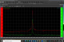
Do you see what I was talking about with the dB reference. You 300Hz signal is about -20dB so the -70dB 3.5kHz is actually -50dB from the signal. This is still a good result when compared to some expensive commercial arms, I have a plot from the Linn Ekos and the first sideband is -40dB. Kuzma et-al don't publish any measurement data in fact no highend tonearm manufacurer does I sispect because they don't measure well.
The harmonic fall off looks excellent in that it's almost a linear decrease.
If you zoom in on the 300Hz fundamental there are a couple of sidebands visible at about -50dB if you want to improve the arm further find out what is causing these and you will hear an improvement in clarity. If you look at the plots in my post #4836 you can see the sidebands at 8.5Hz -47dB. These were caused by the OEM CW and its dynamic damping, basically decoupled CW. I made a new CW and stub that rigidly locked and the sidebands just about disappeared.
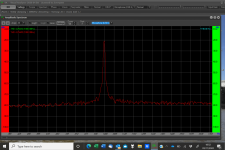
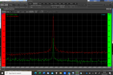
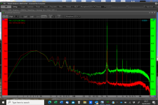
I measured before I started this work and after, here attached are the measurements. the slightly "sharper" spike is due to better motor mounting which I did at the same time and the other channel showing the crosstalk is just a difference in how I set the measurement.
A worthwhile improvement in my opinion.
M
Attachments

As many of you will have already worked out, i meant to write stylus to spindle, my RTA has pivots on its vertical articulation mechanism but that's not what i meant or have done here!After some work on the plinth below my TT and TA they are now effectively much better coupled so that the path from the stylus to the pivot is as rigid as possible.
I measured before I started this work and after, here attached are the measurements. the slightly "sharper" spike is due to better motor mounting which I did at the same time and the other channel showing the crosstalk is just a difference in how I set the measurement.
A worthwhile improvement in my opinion.
M
M
Evening All,
I have left you all in peace for far too long without tormenting you with my rubbish!
So here goes.
Now, under my RTA i have a Victor TT 81 (with my version of a plinth) which seems to give better speed stability after rebuilding the motor (damaged in transit and loose sensors) with a lot of help from my friends.
The RTA is fundamentally the same as recently but carries an AT VM 95e in order to later try out some better MM cartridges, again as encouraged by my friends. So I built Rod Elliotts PO6 MM pre, on battery power and set it all up. this seems as good in tracking and sound as before, so i now hope to try better MM cartridges and see if i hear some magic now..............
So please have a look as it rides the torture test attached.
Sorry about the mm indicator stuck crooked on the front of the cartridge, i should have put it there before assembly and was tricky to tuck it in later to see displacement.
If anyone is interested i can bore you with many more pictures!
M
Attachments
Seems a relaxed ride on a roller coaster well beyond RIIA specs. Very near to that of a very good pivoted TA, and very difficult to find instead on linear ones, especially considering the compliance of the AT95, the prototype of mid/high compliance average cartridges.
My congratulations, your RTA came to an outstanding mechanical behavior, the first basis to evaluate every kind of TA, imo
carlo
bore us with more pictures/ video/ physical measures, please
My congratulations, your RTA came to an outstanding mechanical behavior, the first basis to evaluate every kind of TA, imo
carlo
bore us with more pictures/ video/ physical measures, please
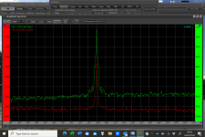
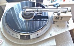
Thankyou for the response Carlo, most importantly it produces good to listen to music for my taste. In order to give a more objective measurement i attach the measurements i have just taken and a pic of the current set-up.
I hope its interesting to everyone.
I believe this is a good working prototype of an RTA, that costs little, doing what its supposed to do, letting the cartridge read the record constantly from the correct orientation with as little interference as possible. i will try and produce a better version but i work with hand tools only, no lathe, pillar drill etc, so its tricky in some ways.
M
Attachments
Looks good Mike. The video is interesting and I don't think many pivoting arms would track this excessive warp/eccentricity any better.
Why don't you do a set of plans/drawings so the DIY community can build this arm.
Why don't you do a set of plans/drawings so the DIY community can build this arm.
I dusted off my LTA and installed it yesterday. I't was originally designed to fit over an SP10mk2 chassis with this naked SP10 the mount is a little untidy but now I have it working and sounding better than my pivoting arm I'll rebuild everything.
Even with the ball race bearings a close look at the stylus on an eccentric pressing showed no deflection. I have ordered bits to construct new pin bearings and new rail.
Even with the ball race bearings a close look at the stylus on an eccentric pressing showed no deflection. I have ordered bits to construct new pin bearings and new rail.
Even more impressive than before, Warren. And sounding better even than your "four points" PLT?
Really remarkable, this thread is reaching state of the art solutions, and not only among diyed realizations, imo.
c
Really remarkable, this thread is reaching state of the art solutions, and not only among diyed realizations, imo.
c
Great to see that Warren, i have always been wondering how the LTA/RTA principle can compare with PTA of different types. Knowing that you have excellent and optimised PTA's it will be good to see how this one compares. Meanwhile, i am hoping to be able to publish some drawings (with a little help from a friend) and hope that some more expert constructors will build some versions and also make some comparisons. I will be trying a different cartridge soon to see what that can sound like.
M
M
The carriage is not ideal for the Grado Opus 3 I had to add a 4mm spacer so the bottom of the carriage cleared the LP. COG is also a mm too high it's very close to coincident with the vertical pivot and needs to lowered 3-4mm. I plan to build a new carriage specifically for the Grado.
The things that need attention are
The rail is not perfectly flat so I will construct a new single piece rail with some 4mm linear shaft not as hard as carbide but I have enough to make a couple of rails and it's much straighter than the carbide rods in my current rail.
The carriage is not perfectly flat and the carbide rings were slightly different OD's so the carriage doesn't sit parallel to the rail, I have ordered more carbide rings.
Even with these small errors it still sounds better now than my PTA's. The major issue I fixed this time was a slightly tilted wheel. With the carriage balanced on the rail I noticed the carriage was bouncing up and down as it moved back and forth on the rail. Vertical movement translated into sideways movement and vice versa. Fixing the wheel reduced this translational movement significantly.
@Mike56 Once I get this LTA and my inverted bearing SP10 motor working I would be interested in building a version of your RTA.
Last year I had an SP10 here for repair which was in a Permalli plinth. I mounted a Pmat AT1010 mk6 with Ortofon Winfield MC so I had the opportunity to listen to it in my system it was very close to my SP10 Resin/Bento plinth with my DIY 4point pivoting arm and Technics ECP-205. Listening to this TT inspired me to build the Permalli plinth which now was very much better than the R/B. A comparison now would have my DIY 4point very much better than the AT1010. I guess what I'm trying to say is that fixing this one small error with my LTA has improved it significantly and it now sounds LESS than my DIY 4point. When I say less I mean it's quite obvious now that there are arm modes missing which colour the sound.
Once we have a drawing properly representing it Warren, which the technical department are kindly working on (just like being back at work!), we can consider if there are any further geometrical, COM, or constructional improvements that might be made.
At the moment one great thing about this RTA is its tolerance, several things allow it to cope with inconsistencies, like the 3 ball track/carriage, which self adjusts/seats to inconsistent rails, it doesn't mean it wont be better with consistent rails, but as everything has a tolerance, this way it will still work well. For example i know from set up that there are some less than perfect areas on my rails, you can see them when doing running tests with the vertical articulation locked off, but i cannot measure them on the rails, they are so small they don't appear to affect the performance.
We are going to have to consider what happens with your deep clamp as well...............
Just thought I'd give an update on my @niffy style LTA.
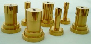
I've spent the last few weeks building a new carriage and pin bearing wheels. Because I used size 4 carbide rings (about 18mm OD) I had to raise the axles 5mm to get the COM of the carriage under the vertical pivot, so the new carriage has a top section to hold the Vee's. COM is slightly under the pivot as tested by the slight increase in VTF as the stylus is raised. A 4mm raise increases VTF 0.1g so riding a warp keeps VTF well within the range of the Grado.
I spent hours on the wheels to get them as concentric as possible. I ended up having to grind the rings as all the sets I have are not round or consistent in thickness. They vary 0.1mm in thickness and have bumps of nearly 0.1mm. The carriage stopped at the same point on the worst wheel. They are now with 0.05mm so significantly better.
1st pic is the original carriage and 2nd,3rd pics are the new one, the difference is pretty obvious.
Next is to complete the new rail, visible in the 2nd pic. This runs 2x 4mm carbide rods in a machined channel. This is designed to replace the composite rail I built which is similar to @niffy rail which is a composite of many parts. I have also ordered some sapphire Vee's to replace the modified M3 setscrews I'm currently using.
Videoing the CL on an off center pressing there is no visible CL deflection with the new carriage.
How does it sound - pretty darn good, I played a couple of LP's today to listen to how it sounded and ended up playing LP's all day.
Warrjon,
It is very nice indeed! Btw, do you have a mechanism to prevent the carriage from dropping off the rail?
It is very nice indeed! Btw, do you have a mechanism to prevent the carriage from dropping off the rail?
Yes the rail goes through the carriage so it can't fall off.
This is the old carriage and has a thicker bottom than the new one.

This is the old carriage and has a thicker bottom than the new one.
Great looking work Warren, and one can guess that your assessment of the sound being "darn good" is also fair even if its not very quantitative!
You often post measurements, how does this one look please? - perhaps in comparison to one of your own excellent PTA's?
Meanwhile, as you know i muck around with an arm where the vertical motion needed for warp acceptance is done with a paralelogram plagiarised from the work of Carlo et al. so as the warp is accepted the cartridge and stylus don't move relative to the direction along the line of the groove.
Looking at the short wand LTA and doing some quick and rough calculations i can see that a short wand pivoting up and down over a sharp 3mm warp over 1/10th of a disc rotation might see a significant effective speed variation as the cartridge sees longitudinal movement relative to the groove as it pivots to accept the warp, the higher the pivot and shorter the wand the worse this is. my calculation says at least + and - 0.5%
How much does this matter in your opinion and would you hear the difference if that was not present.
Of course, no warp=no problem............
M
Looking at the wheel pivots i can see the threaded cup screw to adjust centering and pressure. is there any "springiness" to take up the tension on the pivot please or is it just the cupped screw adjustment?
M
M
Hi to all. There is such an interesting technology as titanium nitride coating. Would you consider it as a proper way to increase rigidity, wear resistance and corrosion resistance of LTA wheels and bearings (as well, as PLA parts)? TIN has rigidity close or equal to that of saphire, so it seems to be able to improve many tonearm parts, even if they are made of softer metalls -making them equal in performance to those made of tungsteen carbide. Another way to increase rigidity of average tonearm tube seems to cover it with TIN layer of several micrometers, ( instead of growing solid artificial saphire tube as respected Frank Cuzma does).
Seems to be a perspective way to go for us -tonearm DIY-ers... Not saying about what TIN coverage looks like pure gold.
Seems to be a perspective way to go for us -tonearm DIY-ers... Not saying about what TIN coverage looks like pure gold.
Attachments
- Home
- Source & Line
- Analogue Source
- DIY linear tonearm