Right, then. I lowered the HT voltage down so that pin 9 showed 100v on the Meter. I put a valve in and now have constant audio from the speaker! Getting somewhere.. It doesn't sound distorted but it's pretty quiet even with the vol pot on full. The speaker isn't in an enclosure so perhaps that's why. Thanks very much for your help
Had audio for about 5 mins then switched it off. When I powered it back up with same situation as before pretty much.
There's something odd going off here, I suspect it's how you have your supply's connected. From the looks of the DC conditions in post #20 it looks like the valves are not conducting, IE there's no current flowing through them. This looks like a heater issue. Have you got a DC bench supply you can use or a 12v wallwart to power the heaters?
Can't figure out the heater situation without more info but I'd start there, you should have a steady rock solid 12 - 13v on the heaters else the amp won't work. LM317's on their own can be tricky when used to regulate a heater supply. On SW on there's a high current draw because the heaters are cold. LM317's can go into protection or oscillate, so I always use a 317 plus a series pass transistor like a 2N3055 or a TIP3055 but any beefy tranny will do. Connect the tranny's collector to the DC supply (make sure you don't exceed it's Vmax), it's base to the OP of the 317 via a 10r resistor, then connect the emitter to your heater, say pin 5, pin 4 to ground.
Can't figure out the heater situation without more info but I'd start there, you should have a steady rock solid 12 - 13v on the heaters else the amp won't work. LM317's on their own can be tricky when used to regulate a heater supply. On SW on there's a high current draw because the heaters are cold. LM317's can go into protection or oscillate, so I always use a 317 plus a series pass transistor like a 2N3055 or a TIP3055 but any beefy tranny will do. Connect the tranny's collector to the DC supply (make sure you don't exceed it's Vmax), it's base to the OP of the 317 via a 10r resistor, then connect the emitter to your heater, say pin 5, pin 4 to ground.
Last edited:
just to clarify, I m getting a constant 13v across the 2 heater pin. But, when I measure the individual pins separately to the negative pin on the ground pin which is fed via the boost converter, i.e. after the smoothing capacitors, I'm getting 60v on 1 and 50v on the other (this is since I lowered the voltage coming from the boost converter.
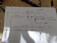
I have the boost converter and the LM317 both wired separately to the DC input jack, parallel. Perhaps this is causing an issue? I will add more pics to show what I mean.
I have the boost converter and the LM317 both wired separately to the DC input jack, parallel. Perhaps this is causing an issue? I will add more pics to show what I mean.


Give that a go. SameHave you got a DC bench supply you can use or a 12v wallwart to power the heaters?
 .
.I am going to go over all the resistors again and make sure the values are definitely correct. Wondering whether to replace the caps incase one has one bad.
It's odd to me that I've built 2 different circuits one with PCL82, and the other with PCL86, using different resistors each time and the result was the same. Eliminated the LM317 being he issue by using a wallwart, tried 2 different boost converters as well. Strange. The only things that haven't changed at the 100uf 400v caps after the boost converter. I have more of these which I can try.
You should have something like the attached "schematic", see attached though it looks like you have a 390r before the cap on the HT supply. First off can you see the heaters glowing in the valve? The 50/60v on pins 4&5 where are you measuring from, or where is the ground? From what I can see your heater isn't connected to the HT ground, this will mean you get odd readings like that.
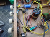
It is a mess as you say which isn't normally a problem but in this case it's making it harder to figure out what goes to where and thus diagnose the problem. Also you wire colour coding isn't helping. Mains wiring in the UK is brown for the live and blue for neutral, only use these colours for mains only. Then use red for your HT, black for grounds, green or another colour for heaters, etc etc. That would help figure out what the craic is. Using a copper wire as the ground bus helps too.
If you lay out your amp neatly keeping resistor leads short as poss this'll help. I know it's just a mock up or prototype but still. Attached is an amp I fixed/re-built for someone to give you an idea.
I also noticed the black heater wire looks a bit loose, have a look at all your solder connections with a magnifying glass to check they're ok or give them a gentle tug.
Lastly there is a reason that you have 0v at both cathodes, I can't see from your pics why that is, find out why and that should help. As mentioned are the heaters glowing, is the valve hot? Using you meter on continuity with the amp turned OFF check you have continuity from each cathode resistor to 0v or ground. Do the same for the HT.
Hope that helps, Andy.
Attachments
Cheers, Andy. I spotted the heater not being grounded to HT ground today. The reason for the mix of brown and red for live is that I only had decent stranded wire in blue and brown, the other wire is solid core stuff I got in a mixed pack. It's a lot harder to work with than the stranded, I've ordered a pack of stranded core hook up wire.
I think what I'm going to do is strip the whole amp again and rewire it again, taking note of points you've raised above and also do it more neatly with sleeving on all caps and resistors etc. I'm also going to build the slow start heater circuit this time.
Re the 390 resistor, this was from the ECL82 schematic I was originally following (see attached). I kept this part the same for the PCL86 power supply as I'm still using the boost converter.
Will post a update. Cheers
Yes, a re-build would be a good idea, a copper ground bus is ideal for a quick lash up as it saves running loads of grounds to one point. If you send me a PM with your address & I'll send you some wire if you pay the postage which will be £3.
One thing I did note was that your HT is a bit low @ 228v, you could do with something more like 300 to 330v depending on how much voltage is dropped by your OP. Anyhoo, that's for later when you get it working.
One thing I did note was that your HT is a bit low @ 228v, you could do with something more like 300 to 330v depending on how much voltage is dropped by your OP. Anyhoo, that's for later when you get it working.

I've rebuilt it again using the schematic from the video with ECL82 valves. I've still only got 1 channel for testing. I've tried to re-do it a bit neater, probably better than last time but still not great. Still not working unfortunately. I have tried measuring the voltages, With the Valve disconnected, I can set the voltage at the boost converter.
As measured with valve removed:
HT 232
pin 1 0v
2 0v
3 0v
4 0v
5 13.3v
6 232v
7 232v
9 227v
With the valve connected, HT is starting off at around 300V on power up, it then starts to drop away quite quickly. The readings are really erratic. I tried feeding the HT tag and the earth tag directly from the boost converter bypassing the smoothing capacitors just to test, the HT voltage was still all over the place.
Valve back in, If I let it het up and then switch the power off, sometimes I'm still hearing audio through the speaker (as before).
Here's a few pics of how its wired up.


I can't see anything wrong apart from you've melted the casing on a few caps, shouldn't stop it working though. Without any more better ideas I think it's your power supplys, every simple low power SE amp I've built has worked straight off bar a few minor issues but this was using linear supply's.
I then had another closer look,
1) has a decoupling cap and a 10m grid leak resistor, 10m is a bit big, 470k or 1m is more usual, wouldn't stop it working though.
2) Has a 470r then another R going to ground, then a yellow wire to pin 8, that's wrong
3) 47k? to ground, wrong.
4) ok
5) ok
before I go on what valve are you using a PCL86 or 82?
PCL82 this time, Andy. as per this Schematic
https://www.diyaudio.com/community/.../1059957-c39d7b4fc6f24c4dae0e234246d14873.jpg
https://www.diyaudio.com/community/.../1059957-c39d7b4fc6f24c4dae0e234246d14873.jpg
Right, that makes more sense but this schematic isn't one I'd recommend as a first build, it could be prone to oscillation. Have you got a scope? It'd be interesting to see if it is oscillating. you could try removing R4, connecting the triodes cathode to a 470r to ground, and is that a 220k anode resistor? Change that for a 47k, then it might work. If it does that'll rule out your power supply as the issue. Hope that makes sense.
Whatever, there's something very wrong if your HT is all over the place, parasitic oscillation could be the cause, without a scope it's hard to tell.
Whatever, there's something very wrong if your HT is all over the place, parasitic oscillation could be the cause, without a scope it's hard to tell.
I've been looking at scopes. I was surprised how cheap they are on Amazon. Probably very basic but might do the job for a beginner?
Basic is all you need but an old analogue scope might be better. Recommending scopes is tricky.
Re your amp, attached is a schematic that is simpler than yours, there's no local FB, just leave off the R&C marked RSL & CSL at first. Oh and leave your pentodes cathode resistors as is, this is just get a stable working ish amp....hopefully, then you can start making changes or re-connecting bits from the first schematic.
Re your amp, attached is a schematic that is simpler than yours, there's no local FB, just leave off the R&C marked RSL & CSL at first. Oh and leave your pentodes cathode resistors as is, this is just get a stable working ish amp....hopefully, then you can start making changes or re-connecting bits from the first schematic.
Attachments
So socket pin 8. That currently has a wire going to the HT tag. Remove that?connecting the triodes cathode to a 470r to ground
Ignore that... Pin 7 has the wire going to ground. Not pin 8.
Last edited:
I'm not sure the attached schematic is for a PCL82, forget the pin numbers, it's more the general layout.
1) Remove R4 on your schematic.
2) Remove the yellow wire from pin 8 and connect a 2k2 from pin 8 to ground.
This removes all the local FB, you should then have
1) 0v or a bit above
2) 10v ish
3)0v
4) & 5) 16v
6)HT
7)HT
8) 2-3v ish
9) 100v ish
Sorry for all the confusion, I'm running around trying to do 5 things at once.
- Home
- Amplifiers
- Tubes / Valves
- First valve amp project