The cathode resistor is important for both the triode and the pentode stages of the amplifier. In the triode stage, it directly sets the quiescent current of that stage, as the voltage across the cathode resistor presents effectively a negative bias to the triode control grid, which is strapped to ground by the input resistor.
In the case of the pentode output stage, the drop across the cathode resistor also biases the control grid negative with respect to ground. Also important in setting the bias current for the pentode is the voltage at the pentode screen grid. The characteristic curves you see displayed in the data sheets for pentodes are generally generated for various values of control grid voltage and a fixed screen bias voltage. I have had instances where the screen grid of a pentode output stage was unbiased due to an uncompleted solder joint - no screen bias, no plate current...
In the case of the pentode output stage, the drop across the cathode resistor also biases the control grid negative with respect to ground. Also important in setting the bias current for the pentode is the voltage at the pentode screen grid. The characteristic curves you see displayed in the data sheets for pentodes are generally generated for various values of control grid voltage and a fixed screen bias voltage. I have had instances where the screen grid of a pentode output stage was unbiased due to an uncompleted solder joint - no screen bias, no plate current...
Glad you solved the fading power issue, can you remind me please what is the OP voltage of the little heater reg before the LM317. The little regulator isn't the best option for powering the heaters, it's a bit on the small side and the reservoir caps are too small I think, we really need to find a better solution for the long term.
Re your mains tfmr, if you send me the dimensions I might be able to knock you up a little ali box/case for it that or put it under the chassis. Heatshrinking it is not a good idea, it will look awful and prevent the tfmr cooling.
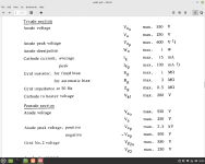
Re the valves operating conditions, download the full datasheet for the complete specs. What you posted and see on the valves main page on the Valve Museum's site is only a small part of the data available. The first place to start with any valve is the "limiting value's" see attached. the full datasheet also gives a couple of "standard" operating conditions for both the triode and pentode section, but you don't have to stick to these conditions. As long as you don't exceed the "limiting values" your ok.
Can you post your DC readings for the amp again please, including the HT at the first big cap - C1 and at the second big cap - C2, voltage out of the heater reg and voltage after the LM317.
Re your mains tfmr, if you send me the dimensions I might be able to knock you up a little ali box/case for it that or put it under the chassis. Heatshrinking it is not a good idea, it will look awful and prevent the tfmr cooling.
Re the valves operating conditions, download the full datasheet for the complete specs. What you posted and see on the valves main page on the Valve Museum's site is only a small part of the data available. The first place to start with any valve is the "limiting value's" see attached. the full datasheet also gives a couple of "standard" operating conditions for both the triode and pentode section, but you don't have to stick to these conditions. As long as you don't exceed the "limiting values" your ok.
Can you post your DC readings for the amp again please, including the HT at the first big cap - C1 and at the second big cap - C2, voltage out of the heater reg and voltage after the LM317.
Attachments
Thanks. I will go over all the voltages again this afternoon and repost.
Re the heater regulator, I agree this isnt an ideal solution. The plan is to replace this with a separate 230v - 12v transformer mounted on the chassis so I can get rid of the laptop DC power supply and just have one, AC power input.
I'll make up another bridge rectifier for the heaters. Should give me not far off the required 16v after rectification in thinking.
Thanks very much for the offer. I'll hang fire for now in that as when I may try another MT before I commit it to the final built chassis. The main concern apart from magnetic shielding is the exposed live conductors. If I do keep it in the final build, I might look at making a bell housing to fit over it which you might be able to advise on?
I've noticed that the MT produces it's own an audible hum at idle and it sounds very similar the hum which is making is way through he signal chain. It's present on the speaker output regardless of the volume pot being turned to off position or fully on, it stays the same loudness.
This MT was probably a gamble and it was taken from a mono tape recorder and probably not intended for the load. It's handling it though and doesn't seem distressed. The buzz is quiet and I noticed it when I was testing the voltages off load on my work bench. It's not getting overly hot, I can touch the casing comfortably when it's been on for an hour under operating conditions.
Might be worth noting that C10 from the schematic was omitted from the circuit entirely. I never initially intended to use a MT so left it out.
I do have it though so could ad it in.

Speaking of the final built chassis, I've found some nice offcuts of seaple mahogany to use for a plinth. Just looking for some aluminum to use for the chassis. Trying to think of something I can reclaim for this purpose but if I can't find anything, it's cheap enough to buy cut to size in the size I need.
I've also got some very nice, no's Bulgin control knobs and bezels which will look great. Same ones Mullard used on their 3-3 and 5-10 prototype amps etc. They where pricey! Need them for another project as well though.
A couple more things I've just thought of...
I tried this with PCL86 valves yesterday (heater voltage adjusted) and the output was barely audible. I've seen quite a few schematics which state PCL86 or 82 for the valves so assumed they where close enough in spec to swap out.
No particular reason for wanting to other than curiosity....
Finally for now, I'm not sure if I'm hearing the tiniest amount of distortion on some vocals. I've been used to listening to a ridiculously clean and probably clinical Aiyima A07 for a while. My main source is digital via a decent DAC, tidal hifi, Spotify premium. I also listen to records on a B&O deck which has built in pre amp.
I have no experience of valve hifi so it might just be a case of unfamiliarity with the way valves sound.
Everything is clear as a bell for the most part and sounds very clear with a sound stage which is far better than I expected. I'm really pleased with the sound. If I listen out for the distortion I can't always really it. I just hear what sounds like a slight distortion every so often.
I might record the sound from the speakers into a pair of condenser mics and post some wavs here at a later stage.
Will post some voltages later today.
Thanks again everyone for your help.
Re the heater regulator, I agree this isnt an ideal solution. The plan is to replace this with a separate 230v - 12v transformer mounted on the chassis so I can get rid of the laptop DC power supply and just have one, AC power input.
I'll make up another bridge rectifier for the heaters. Should give me not far off the required 16v after rectification in thinking.
Re your mains tfmr, if you send me the dimensions I might be able to knock you up a little ali box/case for it that or put it under the chassis. Heatshrinking it is not a good idea, it will look awful and prevent the tfmr cooling.
Thanks very much for the offer. I'll hang fire for now in that as when I may try another MT before I commit it to the final built chassis. The main concern apart from magnetic shielding is the exposed live conductors. If I do keep it in the final build, I might look at making a bell housing to fit over it which you might be able to advise on?
I've noticed that the MT produces it's own an audible hum at idle and it sounds very similar the hum which is making is way through he signal chain. It's present on the speaker output regardless of the volume pot being turned to off position or fully on, it stays the same loudness.
This MT was probably a gamble and it was taken from a mono tape recorder and probably not intended for the load. It's handling it though and doesn't seem distressed. The buzz is quiet and I noticed it when I was testing the voltages off load on my work bench. It's not getting overly hot, I can touch the casing comfortably when it's been on for an hour under operating conditions.
Might be worth noting that C10 from the schematic was omitted from the circuit entirely. I never initially intended to use a MT so left it out.
I do have it though so could ad it in.
Speaking of the final built chassis, I've found some nice offcuts of seaple mahogany to use for a plinth. Just looking for some aluminum to use for the chassis. Trying to think of something I can reclaim for this purpose but if I can't find anything, it's cheap enough to buy cut to size in the size I need.
I've also got some very nice, no's Bulgin control knobs and bezels which will look great. Same ones Mullard used on their 3-3 and 5-10 prototype amps etc. They where pricey! Need them for another project as well though.
A couple more things I've just thought of...
I tried this with PCL86 valves yesterday (heater voltage adjusted) and the output was barely audible. I've seen quite a few schematics which state PCL86 or 82 for the valves so assumed they where close enough in spec to swap out.
No particular reason for wanting to other than curiosity....
Finally for now, I'm not sure if I'm hearing the tiniest amount of distortion on some vocals. I've been used to listening to a ridiculously clean and probably clinical Aiyima A07 for a while. My main source is digital via a decent DAC, tidal hifi, Spotify premium. I also listen to records on a B&O deck which has built in pre amp.
I have no experience of valve hifi so it might just be a case of unfamiliarity with the way valves sound.
Everything is clear as a bell for the most part and sounds very clear with a sound stage which is far better than I expected. I'm really pleased with the sound. If I listen out for the distortion I can't always really it. I just hear what sounds like a slight distortion every so often.
I might record the sound from the speakers into a pair of condenser mics and post some wavs here at a later stage.
Will post some voltages later today.
Thanks again everyone for your help.
I looked in my stash today to see if I had anything better for your heater supply. I have a couple of old laptop supply's, switch mode 19v 4A ish and a 14v 3A AC wallwart which when rectified could give you 189v DC which you can then regulate with your LM317, they're free if you want them.
Re the noise hum of your mains tfmr, it's looks like a budget tfmr so might be a bit noisy as it was built to a cost, you could try tightening the metal clamp to tighten the laminations.
Re distortion, in a PM I recommended a bit of free software called "Soundcard scope" see - https://www.zeitnitz.eu/Scope_en . this is free software, very easy to use and has a very low THD sig gen, scope, FFT and distortion meter all in one package. The distortion meter is as accurate as my HP8903B audio analyser. If you download, set it up, then knock up a simple resistor divider, say a 10k and 1k resistor, put this is in parallel with your dummy load so you don't overload your soundcard. This will show you how much THD your amp has as well as how much 50hz, 100hz, etc you have.
Re aliminium plate, PM me the size you need and I can sell you a bit of 2mm sheet. I can pre punch the valve base holes if you want.
Re the PCL86, it isn't swappable with the PCL82, it's a different pinout.

Thanks again, DA. I think in going to try and keep it all MT for easiness.
The 230 - 12-0-12 MT arrived yesterday. I've installed it and knocked up a bridge rectifier to supply the heaters. Output after rectification was 21V DC. I'm putting this down to the fact that the mains voltage here is getting on for 250 volts. I is the inputs higher than obviously the output will be?
I'm just looking at RC filters to get this down to 16V.
You both mentioned 'RCRC' filters in relation to he B+ voltages. Is this just 2 RC filters one after the next?
Anyway, I'm using an online calculator to work out the values I need for the capacity and the resistor for the heaters RC filter. For the frequency value, is that just 50?
Providing the above his correct, this is the closest I've been able to get it.

I will take a reading of all the voltages once I've got the heaters running off the new MT.
Can't wait to ditch the laptop power brick for good 🤣
The 230 - 12-0-12 MT arrived yesterday. I've installed it and knocked up a bridge rectifier to supply the heaters. Output after rectification was 21V DC. I'm putting this down to the fact that the mains voltage here is getting on for 250 volts. I is the inputs higher than obviously the output will be?
I'm just looking at RC filters to get this down to 16V.
You both mentioned 'RCRC' filters in relation to he B+ voltages. Is this just 2 RC filters one after the next?
Anyway, I'm using an online calculator to work out the values I need for the capacity and the resistor for the heaters RC filter. For the frequency value, is that just 50?
Providing the above his correct, this is the closest I've been able to get it.
I will take a reading of all the voltages once I've got the heaters running off the new MT.
Can't wait to ditch the laptop power brick for good 🤣
Wrenchone, I remember you saying set the frequency to a tenth of the mains frequency? That would give me this...

After playing around with different value resistors, it's now running on the 12v transformer via diode bridge. Will post the voltages for the whole amp later today.
Yep, tfmr/linear supply is better, far more reliable.
My mains is about 246v RMS so yes, higher IP V = higher OP V in regards to the tfmr.
Re dropping R, using ohms law you have 21v, you want 16v, are you using the LM317 here?, so, if no LM317 we need to drop 5v, so 5v/0.6A = 8.3r I make but thats if valves are connected in parallel, if heaters connected in series, then 5v/0.3 = 16r ish, but you'll find you may need to experiment so try a 10r or 22r and you should be about right. A 5 - 10w jobbie should be about right, again experimentation will help suss this out. You can just power the heaters only for a short test.Yes, it's 50hz but it doesn't specify if rectified, in which case it'd be 100hz.
Re RCRC filter, yes, it's just one RC filter after another or you could use an RC filter then two RC filters per channel.
I think the last thing I tried was a 3r3 which got to 10ish VDC. Which, actually worked enough to produce music but I can't imagine it will do the valves much good in the long run... I am getting low on resistors so wil order more of a selection to play around with. I only have 2w as well so I'll get some 5w ones this time around.
The heaters are wired in Parallel. I was using using 50hz in he calculator.
All good learning!
The heaters are wired in Parallel. I was using using 50hz in he calculator.
All good learning!
When I've checked the rectified DC voltage for the heaters again, it's coming out at just over 16v. That's with the RC filtering part removed, measured on the diode legs, (off load). I'm sure I measured 21v yesterday 
Anyway...
I decided to use this to supply the valves directly without filtering (still in parallel) and measure the voltage and pins 4 and 5. It's coming out at around 10v on each valve. I thought in parallel, the the voltage would stay at 16v?
Anyway...
I decided to use this to supply the valves directly without filtering (still in parallel) and measure the voltage and pins 4 and 5. It's coming out at around 10v on each valve. I thought in parallel, the the voltage would stay at 16v?
Any DC supply must have a rectifier and at least one cap. If you rectify AC with just a bridge rectifier you won't get 100% DC. Any power supply that delivers a rectified DC current will have to some extent an AC component or ripple voltage, see the attached image (courtesy of Lenard Audio Institute, see -http://education.lenardaudio.com/ ). It's a HT supply but the same physics apply. Without getting into the subject in more depth covering peak, RMS etc your heater supply isn't up to the job, you need a reservoir capacitor. This is why you are getting "odd" readings.
Right, experiment time.... connect a bridge rectifier to the winding on your tfmr, measure the voltage from the + & - on your bridge. Next connect a 20r or two 10r resistors from + & -, measure V. Now bung a capacitor after the bridge, measure V, then connect your resistors, again measure V. All four readings will be different, figure out why, do your research.
There's loads to cover here but most of it is basic electronic theory, which your weak on at the moment, which is cool, we all started out knowing b*gger all.Gen up on AC v's DC current, rectification & series parallel connection of components.
Attachments
Out of interest, what is the current rating for that 12-0-12 winding? There are lots of permutations of connection of windings and tube heaters, and maybe there is a more optimum combination.
For instance, do you use the center tap with your bridge rectifier? If you use two diodes and the center tap that is an alternate supply.
For instance, do you use the center tap with your bridge rectifier? If you use two diodes and the center tap that is an alternate supply.
Hi, Hector. I just connected the 4 diode bridge rectifier between 0 and 12. I have been doing some further reading up on rectification tonight and have seen the advantage of using the centre tap as you describe with 2 diodes instead.
The specs for the transformer are
* Power Rating: 6VA
* Primary Voltage: 230V
* Secondary Voltage: 2 x 12V
* Regulation (%): 24
👍
DA, I'm reading up trying to further my knowledge. It's a steep learning curve! Wish I had more time but it's building up slowly, piece by piece.
I will try that experiment 👍
I think you may be on a highway to nowhere. Each PCL86 requires 4VA if you ignore rectification and smoothing losses: 300mA * 13.3VDC.
One of those traffos per tube might be doable, but then why not get one with the right secondary voltage and power output instead, and just connect it directly to the heaters? This make do and mend approach is a waste of precious time and energy.
One of those traffos per tube might be doable, but then why not get one with the right secondary voltage and power output instead, and just connect it directly to the heaters? This make do and mend approach is a waste of precious time and energy.
Seems you are making progress, but I would have recommended (and still suggest you might rethink) to use ECL8x rather than PCL8x, because the 6.3V heater is standard and would allow you more flexibility if you needed to change the design later. For example, you might prefer an ECC82/EL84 combo but I agree for a first outing a triode-pentode is suitable. A 6V transformer would be easier to source probably as a 6V rather than 6.3 though.
Also your idea of a perspex chassis is novel, but may cause you some hum pickup as valves work with high input impedances and don't need much stray signal to interfere. A classic ally chassis which could have a wood surround would have been my suggestion, though the perspex idea makes it a work of art as much as an amplifier.
Also your idea of a perspex chassis is novel, but may cause you some hum pickup as valves work with high input impedances and don't need much stray signal to interfere. A classic ally chassis which could have a wood surround would have been my suggestion, though the perspex idea makes it a work of art as much as an amplifier.
Cheers. I'm not intending to leave this in the perspex chassis, it's just for messing about with. My intention was always to rebuild it into an aluminium chassis once I'm happy with it.
I am indeed making progress. I'm enjoying playing with it! The original idea was to avoid using a mains transformer and power it from a notebook power supply with a boost converter for the HT and step down buck converter for the heaters (as per the YouTube video I was following). I couldn't get the boost converter to cooperate (despite using the same one as the videos author...). I tried 2, both had the same issues.
So I've ended up having to go with a MT for HT Voltage which has opened up a can of worms (esp with regards to the PCL's 16v heaters...). If the boost converter had worked, it would have been job done already. But, I've at least proven to myself that I'm capable of constructing it. I'm happy for now.
Probably but he's learning a lot. One tends to learn little with a straight forward build. A lot of us here have a few years under our belt and have built a good few amps so we know what works for us, a beginner has to learn all this, this project shows the possible flaws and pitfalls inherent in following a schematic pulled off the web.I think you may be on a highway to nowhere
Last edited:
- Home
- Amplifiers
- Tubes / Valves
- First valve amp project