Hi Everyone,
After many years of slow build, I was finally ready to bias my Amp. Due to my limited knowledge of V, I, R and P 🙂 I was expecting failure with PSU itself but it was a smooth ride until now.
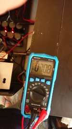
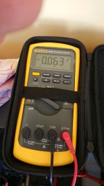
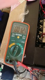
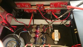
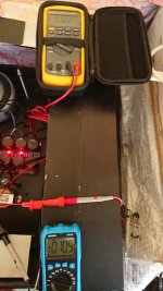
DMM
Blue - Connected to P-Channel
Yellow - Connected to N-Channel
Orange - Connected to O/P from FE Board and Ground from FE and PSU to measure DC Offset.
Using Cascode BD139/140
Matched JFET and O/P devices myself.
PSU Voltage : +/- 44V DC
No Diodes on the O/P boards.
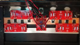
In the images, only the lower boards are connected, upper ones I did not connect as I was not confident that I'll be able to bias it without burning anything.
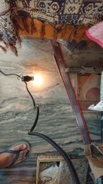
Connected bulb tester and it worked as expected, started bright and then dimming until no light. PSU was/is working fine.
Then started biasing the Amp with bulb tester connected.
-Suddenly smoke appeared magically, I couldn't even tell where it came from as there are no signs of any burning (Now I know why they call it Magic smoke).
- Power inlet fuse is also burnt.
Any help would be appreciated. My knowledge on electronics is limited, but if you can tell me which component, pin and what to measure I'll be able to share that information.
Thank you
After many years of slow build, I was finally ready to bias my Amp. Due to my limited knowledge of V, I, R and P 🙂 I was expecting failure with PSU itself but it was a smooth ride until now.
DMM
Blue - Connected to P-Channel
Yellow - Connected to N-Channel
Orange - Connected to O/P from FE Board and Ground from FE and PSU to measure DC Offset.
Using Cascode BD139/140
Matched JFET and O/P devices myself.
PSU Voltage : +/- 44V DC
No Diodes on the O/P boards.
In the images, only the lower boards are connected, upper ones I did not connect as I was not confident that I'll be able to bias it without burning anything.
Connected bulb tester and it worked as expected, started bright and then dimming until no light. PSU was/is working fine.
Then started biasing the Amp with bulb tester connected.
- No light in bulb once capacitors charged.
- As I started increasing resistance P1(Measured between TP1 and TP2), the voltage on test point on the O/P boards started increasing as did the offset.
- Increasing resistance P2(Measured between TP3 and TP4) brought offset close to zero.
- Kept doing this until voltage reached around 0.070 V, took pictures.
- Kept moving trim pots until I reached nearly 0.100 V on the P-Channel, and 0.093 V on the N-Channel. At this point bulb was lit (not the brightest as in attached image).
-Suddenly smoke appeared magically, I couldn't even tell where it came from as there are no signs of any burning (Now I know why they call it Magic smoke).
- Power inlet fuse is also burnt.
Any help would be appreciated. My knowledge on electronics is limited, but if you can tell me which component, pin and what to measure I'll be able to share that information.
Thank you
Attachments
Hello captJackSparrow,
you can not bias up an amp as long the dim-bulb-tester is connected. You get wrong readings on your DMMs (too low).
You use the dimbulbtester only for first switch-on if there is a short in your new built circuit.
I think you have biased up correctly ( you wrote 0,100 V over P-Mosfet and 0,093 V over N-Mosfet), but you did with the
dimbulbtester already connected - that was the mistake - I think.
Cheers
Dirk
p.s.. I think it would be better to ask your questions in the F5-turbo -builders -thread:
https://www.diyaudio.com/community/threads/f5-turbo-builders-thread.207103
instead of starting a new thread
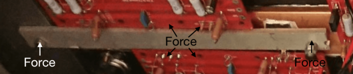
There are basic construction issues here.
The main issue is the retaining heatsink bar and the way it is fitted.
If you think about levers of the first angle; if you tighten the fixings the centre of the bar will lift, due to leverage and cause no cooling to the inner fets as the pressure is removed.
Sort that basic issue out and it might work.
Attachments
Hello captJackSparrow,
you can not bias up an amp as long the dim-bulb-tester is connected. You get wrong readings on your DMMs (too low).
You use the dimbulbtester only for first switch-on if there is a short in your new built circuit.
I think you have biased up correctly ( you wrote 0,100 V over P-Mosfet and 0,093 V over N-Mosfet), but you did with the
dimbulbtester already connected - that was the mistake - I think.
Cheers
Dirk
p.s.. I think it would be better to ask your questions in the F5-turbo -builders -thread:
https://www.diyaudio.com/community/threads/f5-turbo-builders-thread.207103
instead of starting a new thread
Thank you.
One question, when I removed the Bulb tester and connected directly, the reading was nearly 0.300 V on the P-Channel and above 0.200 V on N-Channel. Is that high at PSU voltage of 44 V DC?
350mv is recommended for 32 V PSU, How do I calculate for 44 V PSU?
Thank you.There are basic construction issues here.
The main issue is the retaining heatsink bar and the way it is fitted.
If you think about levers of the first angle; if you tighten the fixings the centre of the bar will lift, due to leverage and cause no cooling to the inner fets as the pressure is removed.
Sort that basic issue out and it might work.
I'll fix that.
Yes, it is high. Your MUR diodes may have started to conduct on the P side, blowing you output section.Thank you.
One question, when I removed the Bulb tester and connected directly, the reading was nearly 0.300 V on the P-Channel and above 0.200 V on N-Channel. Is that high at PSU voltage of 44 V DC?
350mv is recommended for 32 V PSU, How do I calculate for 44 V PSU?
From now on you should do nothing without planning every step with support from forum members. This is a dangerous amp.

^ @andynor They didn't include the diodes per below and verified in pictures in post #1.
Two things...
And...
Where are the thermistors in your picture? I cannot see them.
Edited to add - Good morning, Dennis. 🙂
Edited again to add - I see the thermistors now, in the picture with the retaining bar removed. Revisit this later.
No Diodes on the O/P boards.
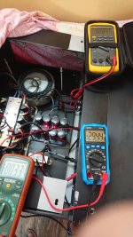
This is just one measurement for each of the boards. Those measurements are fine, but it does not tell the full story of all the FETs on each of the boards.Hi Everyone,
-Disconnected the bulb tester and connected regular wire and P-Channel was reading 0.304 V and N-Channel was reading less than 0.200 V and dropping. The N-Channel voltage was dropping whereas the P-Channel was at 0.304.
Two things...
Do this... Then you can measure across the source resistors of each output device (after necessary repairs) to see if they're all conducting evenly.There are basic construction issues here.
The main issue is the retaining heatsink bar and the way it is fitted.
If you think about levers of the first angle; if you tighten the fixings the centre of the bar will lift, due to leverage and cause no cooling to the inner fets as the pressure is removed.
Sort that basic issue out and it might work.
And...
Where are the thermistors in your picture? I cannot see them.
Edited to add - Good morning, Dennis. 🙂
Edited again to add - I see the thermistors now, in the picture with the retaining bar removed. Revisit this later.
Last edited:
Good morning Patrick. 🙂
@captJackSparrow : Please fix the mounting issue JonSnell pointed out,. You need a few more screws/nuts to ensure uniform and adequate pressure on the mosfets onto the heatsinks. How did you match the mosfets by the way? While you have the output boards off (to work on the mounting bar), please check the bottom of the mosfets for damages. Since you matched the mosfets yourself, you probably have spares and sadly you may need them. 🙁
What insulators are you using for mounting the mosfets?
First of all Thank you everyone.
One of the MOSFET wasn't touching the heatsink completely.
Please fix the mounting issue JonSnell pointed out,.
Yes
How did you match the mosfets by the way?
Had everything matched 4-5 yrs back using the document(https://www.firstwatt.com/pdf/art_matching.pdf), I have spare.
While you have the output boards off (to work on the mounting bar), please check the bottom of the mosfets for damages.
Sure
What insulators are you using for mounting the mosfets?
Mica
Measured resistance TP1 and 2 TP3 and 4, the trim pots are kaput.
How do I test MOSFET and JFET(BD139/140 and the Toshiba one's)
If MOSFET gives correct Vgs, does that mean its good?
Same for JFET?
I am assuming capacitors(Not the PSU, PSU is working fine) and resistors are good, since there is no burning signs.
Issue : N Channel MOSFET was lifting up due to which it developed metallic measels during baising and the magic smoke. Tested components, found one more P channel MOSFET kaput, replaced and biased to 300mV
Will increase to 350mV once I have the lid 😀
The DC offset won't stay at zero. Drifting +/-10mV so far. Is that ok?
Now onto my ALEPH2 of my FELPH25T and then the speakers.
Thank you everyone.
Will increase to 350mV once I have the lid 😀
The DC offset won't stay at zero. Drifting +/-10mV so far. Is that ok?
Now onto my ALEPH2 of my FELPH25T and then the speakers.
Thank you everyone.
Attachments
Last edited:

Hello captJackSparrow,
the fluctuating DC-offset at speakeroutput of arround +-10mV is nothing to worry about.
After 30 minutes of warm up - does it still fluctuate? There should be nothing connected to the input (perhaps a short-plug)
and no speaker connected.
You have pretty high railvoltage ( around +- 42 V DC, if I remember right?). Similar as my F5T. I would test it for temperature
at the heatsinks after 30 minutes of warm up (at your bias of 300 mV over one bias -resistor). Temperature of the heatsink should be around 50° C (55° C absolute maximum). If you are below 50° C, then I would go very slightly higher - in small steps.
Let's say to 330 mV over bias-resistor. Let the amp cook for 30 minutes, then measure temperature of your heatsink.
Don't forget, that closing the toplid will also increase your temperature in your amp!
Don't be too fast!!! Patience is your friend - or next repair... 🤔
Cheers
Dirk 🙂
Enjoy the sound
Dirk brought up a good point regarding the thermals.
With your case complete and lid on, the temp will be higher. You need to monitor the temp of the heatsinks and cook and monitor the bias with the lid on and only remove the lid briefly for adjustments. And you need to do that slowly and let things cook between adjustments.
With 42V rails, you are looking at a about 30W per device with 0.35V across the source resistors (equivalent of 0.5 ohm). That's a reasonable place to stop.
Thank you Guys
I think I waited 20 minutes, will do extenstive test before increasing bias.
Offset was moving towards negative value. I readjusted to zero, after some time it was again negative, it was moving with increasing temperature.
I measured around 40 Degree C before I shut it down after 20 mins. Bias voltage was pretty much around 300mV, didn't drift much with increasing temperature.
After 2 Hour of cooking, results( I don't have the lid at present thats why stopped at 300mV)
DC offset started with +30mV and now its - 11mV
Bias voltage started at 0.283mV and now its 0.303mV
Heatsink at 50 C, no air movement at present on my worktable, just blowing air by hand lowers the DC offset. Ambient temp 24 C.
DC offset started with +30mV and now its - 11mV
Bias voltage started at 0.283mV and now its 0.303mV
Heatsink at 50 C, no air movement at present on my worktable, just blowing air by hand lowers the DC offset. Ambient temp 24 C.
Attachments
Yup. Then fire up without dim bulb = way to high?Hello captJackSparrow,
you can not bias up an amp as long the dim-bulb-tester is connected. You get wrong readings on your DMMs (too low).
You use the dimbulbtester only for first switch-on if there is a short in your new built circuit.
I think you have biased up correctly ( you wrote 0,100 V over P-Mosfet and 0,093 V over N-Mosfet), but you did with the
dimbulbtester already connected - that was the mistake - I think.
Cheers
Dirk
p.s.. I think it would be better to ask your questions in the F5-turbo -builders -thread:
https://www.diyaudio.com/community/threads/f5-turbo-builders-thread.207103
instead of starting a new thread
Thus smoke released.
Bubba
- Home
- Amplifiers
- Pass Labs
- F5 Turbo V3 Magic Smoke