Thank you very much for this idea. I am going to follow it and report the result.
I guess I am soldering the cap and the resistor with DS1833 removed. After soldering the cap and the resistor I am firing the SG4. Then I am removing both components and replacing them with DS1833 back. Is my understanding correct?
I guess I am soldering the cap and the resistor with DS1833 removed. After soldering the cap and the resistor I am firing the SG4. Then I am removing both components and replacing them with DS1833 back. Is my understanding correct?
Remove it, add the C and R, and retest. However you have also probed the DS1833 output and it seems correct, so this is probably not the issue
Removed the DS1833. Connected C and R. Fired it up. No change. All segments lighted again. Although upon switching it off I saw FAC visualized on the display as running lights. Removed the C and R added DS1833 back on board, fired it up and the same. All segments on. Measured DS1833- it is running upon switching on.
Checked-double checked-triple checked the microprocessor orientation? Not from the label, but the identifying mark on the package.

Absolutely. There is no chance to put it differently. It is correctly seated in the socket. Also checked every single small connector inside the socket and they all seem perfectly straight. No bent pins on the chip itself too.
OK. I didn't quite understand from your post #1277, do you still have a working one from before? Or is this now one of the failed ones?
I notice in your picture you are connecting DS1 from the underside - are you sure you haven't flipped the connections? Use a multimeter to verify it is connected as if it was directly placed on the topside.
I notice in your picture you are connecting DS1 from the underside - are you sure you haven't flipped the connections? Use a multimeter to verify it is connected as if it was directly placed on the topside.
Yes, I have a working SG4 but it is at my country house driving an old Lenco 78. So I have no direct access to a working controller right now.
When it comes to the display- yes it is connected properly. Checked with a multimeter point by point. ven thought in the beggining that the display got faulty, but once hitting standby button and seeing nothing comes out of the generator started investigating further.
When it comes to the display- yes it is connected properly. Checked with a multimeter point by point. ven thought in the beggining that the display got faulty, but once hitting standby button and seeing nothing comes out of the generator started investigating further.
OK. Not having one myself, I'm afraid I'll now have to defer to someone with experience of testing this device, sorry.
A little strange that the voltages on U5 pin3 differs from 1,5, and 9. It might be worth removing U5 and trying again,
just in case it's pulling U1 pin6 down.
just in case it's pulling U1 pin6 down.
Thank you for your input. I will exchange U5 tomorrow and will report back the result.
Probably need to purchase another one as the ICs I have are from the same batch and both of the PCBs I build suffer the same symptoms.
Probably need to purchase another one as the ICs I have are from the same batch and both of the PCBs I build suffer the same symptoms.
If both of your builds have exactly the same issue then it does look like a suspect part. Why not wait until your new parts arrive before making any more changes
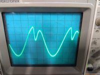

Looks like the output is clipping into an inductive load, can you reduce the amplitude a little and see what the effect is?
Are you using the MA3 amplifier? If so, are you using the BLDC motors recommended?
Its worth also checking the power rails.
The more info you can give us the more help we can provide.
Are you using the MA3 amplifier? If so, are you using the BLDC motors recommended?
Its worth also checking the power rails.
The more info you can give us the more help we can provide.
Now I have done some investigation. All works fine if I just adjust ampitude one step from 128 to 127 and all way down to 64. No clipping. So when I put it on it start with the clipping shown above but sets as fast as it loads the current settings. An sec or two. I use a highvoltage probe with a minimum of 1Mohm load, so I think that is not a problem. I also measured direct at the SG4 board. I have now also tried to load it with ampifier and transformers to 110V and all that works just fine. So not a big issue but seams to do some clipping at full voltage 5v p-p and if i just adjust it to any other value exept 128 it works fine.
A small update.
I have purchased another set of parts from Farnel.
Build 3rd PCB with the freshly obtained parts.
The generator showed exactly the same symptoms.
Started to measure. All chips measures the same voltages as before.
While I put one of the probes of the multi-meter between C9 and R9 I saw that the display started to flicker showing STBY.
Switching the DC OFF and then ON shows the same 8.8.8.8 on the display.
Please see the video
https://media.giphy.com/media/v1.Y2.../nht9tU9QapBLbtaGDn/giphy-downsized-large.gif
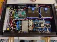
Can you check the values of C9 and C10, they're only supposed to be 10 Picofarad, but looking at your picture
they seem to be similar in size to C11,12 and 13, which are 0.1 Microfarad.
they seem to be similar in size to C11,12 and 13, which are 0.1 Microfarad.
Thank you very much for you reply.
I am very ashamed to say but after you told me to check the 10pf caps I saw that the crystal I mounted is not 18.432 mhz but 1.8432 mhz.
The caps are 10pf.
I will buy the right xtal on Monday and will test. Hope this was the problem and the generator will work.
What is strange is that I am seeing that I ordered the right part (18.432) but the xtal in the bag was wrong frequency and I didnt bothered to check.
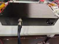
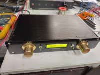
My object is taking chape... I have a homemade turntable with the 110V Premotec motor and wanted to have a nice arrangmenent for it. Its a SG4 and a tachometer built on Arduino. Both charing the same display.
Attachments
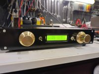
Lovely build.
How did you managed to use one display both for the SG4 and Arduino?
How did you managed to use one display both for the SG4 and Arduino?
- Home
- Source & Line
- Analogue Source
- DIY 4 Phase Sinewave Generator for Turntable Motor Drive