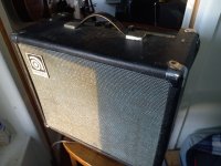
In the barn find of the day, picked up this Ampeg guitar amp. Was making a loud hum. Opened it up and found this exploded capacitor, which is nice to see, because you know the problem is going to be solved in two minutes and you don't have to hunt for it.


Looking at the amp, I wondered whether it would benefit from more modern transistors? I got this feedback about an Akai tape machine not long ago. It looks like it has BC169B, 2N4062 and 40623, 40625 transistors.
Helpfully, Ampeg glued the schematic to the bottom of the chassis, and labels everything on the circuit board -- gotta love that.
Relatedly, the hiss is very pronounced with volume and treble up. It does have carbon comp resistors, lots of them. Where would be a good place to start to reduce hiss? Resistors that go to ground? Others have said this amp is quiet when in good condition. Like my solid-state Fender, the reverb hums a lot.
Any feedback welcome. Here's the schematic.
Attachments
Last edited:
Hi szegedin,
I was curious about what would explode an 0.047 cap and discovered it is C32 in the schematic and connects one side of the line voltage to audio ground. This unnerves me; what if C32 had shorted and connected the hot side of line voltage to audio. Potentially lethal! Something dramatic must have happened to deliver explosive power to C32. I invite comment from other members, but my advice is to remove C32 from the circuit. If hum or EMI becomes objectionable, surely there's a less dangerous way to address the problem. (With C32 gone, reverb hum might improve. Long shot.)
Re the hiss--- more interesting technically. Does hiss level become tolerable when volume is set to zero? If so, this indicates the hiss originates in the first stage and that improving 1st stage noise figure will yield good improvement.
From a noise figure perspective, the first stage looks very noisy; R1 and R2 are very large and are obvious thermal noise sources in their own right. Q1 is likely to have large current noise and it will be exacerbated by large R1 and R2 values. First order of business is your verdict re acceptability of hiss at 0 volume.

@BSST Thanks for your comments. You are bang on right about R1 and R2. Just last night I noticed that they are 120k and -- like my Fender tube amp -- I thought they can and should be lower. I dropped a 47k in parallel to R2 to bring it to 33k, and on the scope at least, that yielded a huge improvement, at least 6db or so.
But it's still a noisy amp! Very little noise with volume at zero. The volume seems not totally linear, but it's acceptable up to maybe 7; same goes for increasing the treble, where most of the noise is (not that part of circuit, I'm just, just the frequency range of the hiss). It's pretty dark sounding until treble is near the top, so that's the main problem.
Poking around with a signal tracer probe and trying to clock signal-to-noise at different stages, it's hard to tell where the noise originates because obviously first stage noise gets amplified. But I think it may be that around Q7-8 it really gets noisy (this is after the treble cap & pot) -- but maybe earlier at Q2. I don't know whether replacing all the transistors could help with noise, but they're cheap so I thought it's worth a shot.
There is some hum at idle, Tried alligator-clipping bigger filter caps, to no effect.
Strangely, it hisses really loud when there is no plug in the input. I think it needs a switched jack on input 1; it has one on 2.
Thanks for your observations on C32. I picked up the amp for peanuts because it was 'blown' and when I opened it up, that violently exploded cap was the first thing I saw; replaced it, and the amp works. Unfortunately, it's not feasible to just take it out of circuit, because a very loud hum results. The cap I had was a 630v cap, replacing the 125v one that was in there, if that helps. 🤷♂️ Everything looks original in there - 47 years old.
Last edited:
A 630V cap at least offers more margin and, at minimum, I would recommend replacing. I don't want anyone to be electrocuted. I still advocate finding a different remedy to the hum problem. We can explore that later.
Perhaps concern about safety is the reason for the large R1 and R2 values--- they would act as current limiters to the guitar player and they are the only path I can spot for faults to earth. Does your amp feature the 3-prong safety line cord? If 2-prong, can you reverse plug orientation and check for improvement re C32 presence? Maybe power transformer has developed leakage. At minimum, add GFI protection.
Do you have a bench power supply that could be used during trouble shooting?
Ignoring safety, from a noise figure perspective, low resistance in R1 & R2 would improve noise figure. Your observation about hiss in absence of input makes perfect sense. This is current noise in the transistor; with no external source, the noise current flows only through R5, yielding even higher noise. A FET instead of a bipolar Q1 might help, but let's no go there yet.
Last edited:
Ha! Yes I thought of that, although I don't know anything about it. Is it possible to swap in a JFET in there? I have another much quieter amp on my bench which made me think of that. Google shows me this: https://www.homemade-circuits.com/how-to-replace-transistor-with-mosfet/ I like to overcomplicate things, but I just would like it reasonably quiet.A FET instead of a bipolar Q1 might help, but let's no go there yet.
I don't have a bench power supply. Wouldn't be surprised if it's leaking voltage. Where should I test for that? It has a three-prong cord. I guess the carbon comp grid stoppers are also supposed to break like a fuse if they get overloaded.
After previous post, I noticed 240V version features 3-wire power cord. Interesting that your 120V version also has 3-prong. Where is safety ground connected internally? I don't find any connection to amp circuit noted.
To test for transformer leakage, I would connect 10K resistor between the two different ground symbols. (I assume a continuity check will show they aren't connected.) Use AC meter range to look for voltage across the 10k; ideally, none of course. C32 has a reactance of about 56k at 60Hz, so you may want to experimentally disconnect it during leakage test.
I overstated source impedance issue earlier since I didn't account for path through R3. Still, it's an issue. If you install a shorting jack at J1, you'll cut signal at J2 input in half.
I'm leaning toward a JFET. It won't be perfect, but better at least.
Old tube amps with 2 wire power used a "ground switch" to find the neutral connection to ~C32. I would toss C32 and install a proper 3 wire power cord.
Remember that a guitar amp needs to have a meg-Ohm input impedance. 100K will short out the high frequencies and it will sound dull. That's why the input uses a bootstrap input, and the 470K load on jack#2 is not a great idea, and that's why musicians never use both jacks. I would also replace C29, C30, C31, and other electrolytic caps. Any large carbon resistors should be replaced because they drift badly, especially if they run warm. More is diminishing returns. I'm not fond of a driver-less amp, so I would probably change that, but there is wisdom in simplicity. If D1 is actually a single diode you will have cross-over distortion but "fixing" that will make it less reliable. Those typical instrument amp tone controls are not great for noise because the tone controls have a lot of loss which requires gain go compensate, compared to a Baxandall tone controls.
Remember that a guitar amp needs to have a meg-Ohm input impedance. 100K will short out the high frequencies and it will sound dull. That's why the input uses a bootstrap input, and the 470K load on jack#2 is not a great idea, and that's why musicians never use both jacks. I would also replace C29, C30, C31, and other electrolytic caps. Any large carbon resistors should be replaced because they drift badly, especially if they run warm. More is diminishing returns. I'm not fond of a driver-less amp, so I would probably change that, but there is wisdom in simplicity. If D1 is actually a single diode you will have cross-over distortion but "fixing" that will make it less reliable. Those typical instrument amp tone controls are not great for noise because the tone controls have a lot of loss which requires gain go compensate, compared to a Baxandall tone controls.
Last edited:
Thanks very much for your comments.Old tube amps with 2 wire power used a "ground switch" to find the neutral connection to ~C32. I would toss C32 and install a proper 3 wire power cord.
Remember that a guitar amp needs to have a meg-Ohm input impedance. 100K will short out the high frequencies and it will sound dull. That's why the input uses a bootstrap input, and the 470K load on jack#2 is not a great idea, and that's why musicians never use both jacks. I would also replace C29, C30, C31, and other electrolytic caps. Any large carbon resistors should be replaced because they drift badly, especially if they run warm. More is diminishing returns. I'm not fond of a driver-less amp, so I would probably change that, but there is wisdom in simplicity. If D1 is actually a single diode you will have cross-over distortion but "fixing" that will make it less reliable. Those typical instrument amp tone controls are not great for noise because the tone controls have a lot of loss which requires gain go compensate, compared to a Baxandall tone controls.
C29, C30, C31 look original; I tried paralleling them with newer caps and it didn't affect anything, so I will probably leave them for now. Good point about R43 & R45 (the big ones) but they do test within range.
Yes the main (only) problem is that it's dark sounding unless you crank the treble, and then it gets pretty hissy. Doesn't sound like there's anything I can do about it.
Thanks for that. I think the three-prong is not original, it's grounded to the chassis at a xformer leg.After previous post, I noticed 240V version features 3-wire power cord. Interesting that your 120V version also has 3-prong. Where is safety ground connected internally? I don't find any connection to amp circuit noted.
To test for transformer leakage, I would connect 10K resistor between the two different ground symbols. (I assume a continuity check will show they aren't connected.) Use AC meter range to look for voltage across the 10k; ideally, none of course. C32 has a reactance of about 56k at 60Hz, so you may want to experimentally disconnect it during leakage test.
I overstated source impedance issue earlier since I didn't account for path through R3. Still, it's an issue. If you install a shorting jack at J1, you'll cut signal at J2 input in half.
I'm leaning toward a JFET. It won't be perfect, but better at least.
Would be really interested to experiment with switching to a JFET - started looking that up, but any help appreciated. Doesn't sound like it will impact noise level though..
Since this thread initially didn't get responses I started another, so they overlap 😏 - https://www.diyaudio.com/community/...b-and-2n4062-transistors.396192/#post-7278031
I suggest a J111 as a JFET replacement for Q1. A Mouser link: https://www.mouser.com/ProductDetail/onsemi-Fairchild/J111?qs=ljbEvF4DwOPfW9b/V2WWZw==
Data sheet claims source and drain can be used interchangeably, so they connect to collector and emitter pads in whatever orientation is most convenient. You will need to reverse the polarity of C2, as the source voltage should be larger than the gate voltage. With any luck, source voltage will be about 13V; let me know what it turns out to be. I hope noise will be lower, but no guarantee I'm afraid.
Per steveu advice, experiment with removing R3 for possible high end improvement. With open circuit at input, amp will still be noisy due to bootstrap bias, but should quiet when source is connected. Reducing R1 value may also help. Series connect back-to-back zener diodes (~5V) from R1, R2, C1 node to ground would add some protection for the FET, but don't add them until noise experiments are successful.
Transformer leakage, hum, and deletion of C32 in concert with safety ground remain open questions.
Good luck.
A coil around a magnet near the strings.I'm not familiar with guitar transducers. What sort of transducer is used?
Because the grid is a "infinite impedance" the custom is to wind many-many turns for more signal voltage. If you know audio transformers, you know that a HI-impedance winding with any practical capacitance will roll-off treble. This is actually used to roll-off the inharmonic overtones of a naked steel string. Resonance with cable from 2.5khz to 6kHz and -12dB/oct beyond.
With a few assumptions, the self-impedance at resonance may be hundreds of kOhms, so a 120k load will suck-off some zing.
However if we trust the schematic, the J1 input is 710k, plenty high. (A bit odd because Jesse or somebody in Ampeg favored 3.3M grid inputs on the tube amps, but maybe this early transistor box needs a mellower loading.)
There's been many changes of fashion since this amp was built. If you want "newer", get a new (or pawn-shop) amp, don't cut-up old irreplaceable stuff.
The death cap was actually rated 125VAC on the side! It is just old, and now a dubious idea.
Guitar pick-ups are massive inductances, up to 10 Henries, so even a 100K load is a low pass filter. Some cheap pick-ups are piezo, which are equivalent to a capacitor in the range of 10nF, so if they are loaded by a low impedance, you lose the low end. The very worst case is a Fender Rhodes piano which is several inductive pick-ups wired in series, so it is very sensitive to loading, so much so that they are known for a dull sound. This is why Less Paul became famous when he wound his own low impedance guitar pick-ups. When I was young, my musician friends were very fussy about their guitar cords. Today I understand that the capacitance of most coax cable is too much for the high impedance guitar pick-ups.Thank you, steveu!
I'm not familiar with guitar transducers. What sort of transducer is used?
The bootstrap follower Q1 hides the loading of the 100K resistors R4,R6, so the input impedance is much higher than 120K+470K. Be sure the bootstrap capacitor C2 is good.
Does anyone locate the preamp stage near the guitar pickup to address cable capacitance? It could be phantom powered like microphones.
Interesting you say that because c2 is the one newer (or older?) looking cap on the board. 🤔My cheesy meter doesn't test capacitance.Guitar pick-ups are massive inductances, up to 10 Henries, so even a 100K load is a low pass filter. Some cheap pick-ups are piezo, which are equivalent to a capacitor in the range of 10nF, so if they are loaded by a low impedance, you lose the low end. The very worst case is a Fender Rhodes piano which is several inductive pick-ups wired in series, so it is very sensitive to loading, so much so that they are known for a dull sound. This is why Less Paul became famous when he wound his own low impedance guitar pick-ups. When I was young, my musician friends were very fussy about their guitar cords. Today I understand that the capacitance of most coax cable is too much for the high impedance guitar pick-ups.
The bootstrap follower Q1 hides the loading of the 100K resistors R4,R6, so the input impedance is much higher than 120K+470K. Be sure the bootstrap
capacitor C2 is good.
Yes many modern basses have 'active pickups' meaning a preamp, but not really for that reason. They say it's not an issue until cable lengths are more than 20', and people playing on big stages just use wireless all the time now.Does anyone locate the preamp stage near the guitar pickup to address cable capacitance? It could be phantom powered like microphones.
BTW is that right that there is 43v on the lead running to the reverb tank? I accidentally shorted it and blew a fuse. Does that voltage have to do with the reverb hum maybe? A bad coupling cap?
I do this for decades. It is called active pickupDoes anyone locate the preamp stage near the guitar pickup to address cable capacitance? It could be phantom powered like microphones.
Excellent observation re reverb enclosure! Can the box be opened and the hot lead brought out independently? Then case could be grounded and better B+ filtering added if beneficial.
Yes for sure. It's wired with the negative insulated from the chassis on the input side, and grounded to the tank chassis on the output side, if I'm not mistaken, as I think usual for reverb tanks. I think it's grounded but maybe not well. So, what do you mean, put a coupling cap in series with the hot lead?Excellent observation re reverb enclosure! Can the box be opened and the hot lead brought out independently? Then case could be grounded and better B+ filtering added if beneficial.
I guess that voltage explains this thing blocking the tank's input lead 😒 I had to order fuses because this thing has a fuse hard soldered in to the circuit board, which shows excessive optimism about the prospect of blowing a fuse.
Thanks for the picture of the internals. It introduces almost as many questions as answers. 😕
The Ampeg schematic sure is skimpy with details. I can't find a board mounted fuse in the schematic or in the picture. Now with the picture, I think I observe RCA phono jacks on both the driving transducer and output transducer; the driver jack isn't depicted at all in the schematic, no enclosure hinted in diagram.
Are the jacks really RCA types, sleeve and center signal? If the driving jack's shell is bonded to the case, I can understand the motivation for floating the case at B+ potential. The schematic seems to indicate one end of the output transducer is grounded; is its output jack really isolated from the enclosure? If the output shell is also bonded to the case, then it's output transducer is also at B+ and C13 is polarized backwards; reverb output would then be in series with +43V, obviously prone to hum. Can you help me understand some of these dilemmas? I'm probably overlooking something obvious. In the pic, which end of reverb is input?
- Home
- Amplifiers
- Solid State
- New transistors (& resistors?) for 70s Ampeg amp?