Okay, with the Chinese 1305 board in OEM , totally unpowered including unplugged USB, I traced all four digital lines (I2s + MCK) from the TDA1305's (there are two in parallel) to the CS8414. These traces are 0-ohm direct. Those Omron relays are there for some other reason. Maybe they are momentary (Normally Closed) muting devices? After DC 5v is applied to mains of the Chinese board, upon inserting a USB jack from the live PC, I can here a monetary click. These seem to the OMRON's in action--whatever that is.The lines seem to go through the relays but hard to say if removing them would help at all.
That does not change the unfortunate fact that the I2S lines seen from the I2S pin header are not properly terminated. That I2S pin header is probably meant for I2S output (i.e. for using other DAC chips).
Could it be that your probe is set to 1x ? For high frequency measurements it should be set to 10x.
Perhaps, you are referring to the occurring phenomena? Yes, until recently, I overlooked it 😉
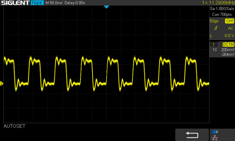
That would explain the rounded edges you are getting.
Exactly. We need to know the probe setting and the other settings. Does the probe have a 1x / 10x switch on it?
Your oscilloscope appears to be a 200MHz Siglent SDS1202x-e. We would like to see a picture saved by the scope that shows its main settings. Right now we don't know sweep rate, the vertical gain, etc., for some of the images you post.
Your oscilloscope appears to be a 200MHz Siglent SDS1202x-e. We would like to see a picture saved by the scope that shows its main settings. Right now we don't know sweep rate, the vertical gain, etc., for some of the images you post.
Sorry ... but you are both confused [Both Dimdim and Markw4] . Look at EXACTLY what you [Markw4] requested in your post (https://www.diyaudio.com/community/threads/xmos-xu208-or-amanero-usb.323116/post-7274948).Exactly. We need to know the probe setting and the other settings. Does the probe have a 1x / 10x switch on it?
Your oscilloscope appears to be a 200MHz Siglent SDS1202x-e. We would like to see a picture saved by the scope that shows its main settings. Right now we don't know sweep rate, the vertical gain, etc., for some of the images you post.
And that is what I gave you-- per your request -- in the followup post.
There is no problem here 😉
Again, go back tho the photobomb post, and the EXACT section of THAT post and where markw4 selected the scope image he request I USB capture.
You asked if we were talking about 'this phenomenon.' We can't read your mind to know if that was the same signal or not. A 'phenomenon' may or may not be referring to a switch setting. Its very hard to know exactly what you are doing when reading forum posts and looking at pictures that do not contain needed information. We are trying to help you here, but we need your help too to make clear what we can't see because we're not there.
Also, we also still can't read the scope settings from the picture. What is the horizontal sweep rate? What is the vertical gain setting? Can you set the scope to display the waveform frequency? Display peak to peak voltage?
It might also help to see a picture of how you have the probe connected when we evaluate a picture of the scope screen. All the little numbers displayed on the scope screen at the top and bottom are also important. Using the scope's screen capture function is the best way for us get more complete information, if you can do it.
Last edited:
Exactly. We need to know the probe setting and the other settings. Does the probe have a 1x / 10x switch on it?
Just look at the pictures with the probe: Clearly at 1x 😱
Confirmation would be nice. We are communicating over a 'noisy channel.' Checksum. Belt and suspenders. You know.
Unclear what "we" means. Are you speaking for some group?We are trying to help you here, but we need your help too to make clear what we can't see because we're not there.
IAC ... the photobomb post , I believe, quite clearly shows the problem: a termination problem -- on all four digital lines -- when the adapter is connected to the Chinese 1305 board.
It's unclear why you are being being distracted by non sequiturs such as "picture of the scope screen" (which I think I captured and presented in the photobomb and other posts clearly enough).
About my remarks in https://www.diyaudio.com/community/threads/xmos-xu208-or-amanero-usb.323116/post-7275282
... the scope image of MCK you selected for further clarification (which I provided in the following post w/ a direct screencapture ) was in fact the MCK waveform of the OEM Chinese board, in situ, w/o the adapter. That is, that MCK is the direct feed from the CS8414, and acts (sounds) normally.
[...]
I think I'm on my own here.
If/when I find a solution, I'll be sure to update this thread.
That may be a mismatch between the actual setting of the probe's switch and the relevant setting of the oscilloscope. We can't be sure.Just look at the pictures with the probe: Clearly at 1x 😱
Looking at the CS8414, I see that (like the 1305) it is a 5V part.Unclear what "we" means. Are you speaking for some group?
IAC ... the photobomb post , I believe, quite clearly shows the problem: a termination problem -- on all four digital lines -- when the adapter is connected to the Chinese 1305 board.
It's unclear why you are being being distracted by non sequiturs such as "picture of the scope screen" (which I think I captured and presented in the photobomb and other posts clearly enough).
About my remarks in https://www.diyaudio.com/community/threads/xmos-xu208-or-amanero-usb.323116/post-7275282
... the scope image of MCK you selected for further clarification (which I provided in the following post w/ a direct screencapture ) was in fact the MCK waveform of the OEM Chinese board, in situ, w/o the adapter. That is, that MCK is the direct feed from the CS8414, and acts (sounds) normally.
[...]
I think I'm on my own here.
If/when I find a solution, I'll be sure to update this thread.
Did you check to see what voltage is powering your 1305s?
What are the voltage levels of the I2S coming out of the CS8414? Closer to 5V or to 3V?
Thanks. Not to mention if it indicates 'BW Limit' next to the vertical gain display....the relevant setting of the oscilloscope.
Oh, you mean here?Just look at the pictures with the probe: Clearly at 1x 😱
Yes, it does look like it is at the x1 position.

Yes, both the Siglent and the probe are at x1.Yes, it does look like it is at the x1 position.
I only "... close your eyes and count to 10".
https://www.cancioneros.com/lyrics/song/998539/listen-what-your-heart-says-praying-mantis
Ground on one board and probe on another board or interconnect? Are more or all of the pics taken that way?
The 1305 section on the Chinese pcb is 5v. Same as the entire pcb. All ICs and LEDs feed off the same single 5v jack. The USB jack also has 5v that must be used (the USB 5v makes the XMOS chip work).Did you check to see what voltage is powering your 1305s?
What are the voltage levels of the I2S coming out of the CS8414? Closer to 5V or to 3V?
-----------------
Volt levels of four digital pins (OEM board, no adapter used. Molex tap used to probe with bench-top OWON XDM2041 DMM. See prev photos)
BCK 1.565 v (audio playing/ not playing indifferent)
MCK 1.36 v (audio playing/ not playing indifferent)
WS 1.565 v (audio playing/ not playing indifferent)
DATA 0.4 (no audio playing) - 0.8 (audio playing)
-----------------
Volt levels of four digital pins (XMOS USB-I2s adapter only; not connected to downstream DAC; Molex tap used to probe with bench-top OWON XDM2041 DMM. See prev photos)
BCK 1.63 v (audio playing/ not playing indifferent)
MCK 1.36 v (audio playing/ not playing indifferent)
WS 1.62 v (audio playing/ not playing indifferent)
DATA 0.13v (no audio playing) - 0.81v (audio playing)
==========
The voltage levels you measured were probably VAC rms measurements which are useless. You should measure the high and low signal levels e.g. with scope at DC coupling.
According to TDA1305 datasheet Sysclk (MCK) should be at minimum 0.8*VDD so 4V with 5V VDD. I2S signals should be at minimum 3.5V (0.7*VDD). Your XMOS board probably has 3.3V levels on digital output pins so it quite likely will not work with your TDA1305 board unless you lower the VDD to below 4V. That would cripple the board as CS8412 requires at minimum 4.75V.
But none of the above fill fix the high noise seen on your scope pictures when using XMOS board.
The high noise may be an artifact due to the non optimal placement of the probe's ground.
And even if it is indeed real it would not justify the dac not working at all. It is not that bad.
But the XMOS I2S voltage levels are definitely incompatible and do justify the dac not working.
And even if it is indeed real it would not justify the dac not working at all. It is not that bad.
But the XMOS I2S voltage levels are definitely incompatible and do justify the dac not working.
You've mentioned this a few times before in this thread.But the XMOS I2S voltage levels are definitely incompatible and do justify the dac not working.
Which voltage levels -- the V_cc on the DAC chip, MCK, BCK, DATA, WS?
Be sure you've gone thru my experiments -- reported prev in this thread and the Naim 1305 thread -- before committing a reply.
- Home
- Source & Line
- Digital Line Level
- XMOS XU208 Or Amanero USB