In this exciting episode we will see how all power triodes have similar Damping Factors.
And how the Output Transformer will reduce that DF further.
Triode Damping Factor & Output Transformer Effect. John L Stewart Feb 2023
1) All Triodes Have Similar Damping Factors (DF)
In Class A the theoretical maximum output for common triodes occurs when the load impedance Rl is 2rp. In a practical circuit it is more like 2.5 rp. But distortion is rather high at that kind of load, a conservative designer might go for a 3rp or even 4rp load Rl.
Damping factor is simply the load impedance divided by the internal impedance of the amplifier. Taking the 2A3 & its specifications given in the RCA tube manuals we have-
At 250V on the plate & -45V on the grid rp of 800R & a recommended load of 2500R. That looks like a Damping Factor (DF) of 2500 / 800 or 3.13.
Another good example is the 10/10Y. In this case the plate is at 425V & the grid at -40. The DF looks like 10.2K / 5K or 2.04. On the low side, the spec is pushing for more power.
The 45 DF at 275V plate is 4600 / 1700 or 2.71.
In each case the DF could be improved by using a higher load resistance.
The signal still needs to get thru the output transformer. How much impedance the OPT will put in the way of the signal depends a lot on how much Gelt ($$$) people want to spend.
2) DF lowered by OPT
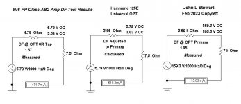
For an estimate of how much resistance an OPT adds to the internal impedance of an amplifier I ran these tests on the Class AB2 PP 6V6 experimental amp I built about 20 yrs ago.
Internal resistance for this was calculated by using the traditional Black Box method. With the signal applied & proper load connected the voltages are measured both Open Circuit (OC) & Closed Circuit (CC). And measurements ahead of the OPT on the plates & on the secondary. The primary side load used was 7K. The secondary 7.5R on taps 3-6, that reflects 6.8K to the plates. The internal impedance is (Eoc – Ecc ) / (Ecc/Rl ). And DF is Rl / Rint. Refer to the diagram.
Comparing the DF results on the OPT primary to the secondary of the OPT indicated the OPT was adding 0.93R to the output terminals.
JLS
And how the Output Transformer will reduce that DF further.
Triode Damping Factor & Output Transformer Effect. John L Stewart Feb 2023
1) All Triodes Have Similar Damping Factors (DF)
In Class A the theoretical maximum output for common triodes occurs when the load impedance Rl is 2rp. In a practical circuit it is more like 2.5 rp. But distortion is rather high at that kind of load, a conservative designer might go for a 3rp or even 4rp load Rl.
Damping factor is simply the load impedance divided by the internal impedance of the amplifier. Taking the 2A3 & its specifications given in the RCA tube manuals we have-
At 250V on the plate & -45V on the grid rp of 800R & a recommended load of 2500R. That looks like a Damping Factor (DF) of 2500 / 800 or 3.13.
Another good example is the 10/10Y. In this case the plate is at 425V & the grid at -40. The DF looks like 10.2K / 5K or 2.04. On the low side, the spec is pushing for more power.
The 45 DF at 275V plate is 4600 / 1700 or 2.71.
In each case the DF could be improved by using a higher load resistance.
The signal still needs to get thru the output transformer. How much impedance the OPT will put in the way of the signal depends a lot on how much Gelt ($$$) people want to spend.
2) DF lowered by OPT
For an estimate of how much resistance an OPT adds to the internal impedance of an amplifier I ran these tests on the Class AB2 PP 6V6 experimental amp I built about 20 yrs ago.
Internal resistance for this was calculated by using the traditional Black Box method. With the signal applied & proper load connected the voltages are measured both Open Circuit (OC) & Closed Circuit (CC). And measurements ahead of the OPT on the plates & on the secondary. The primary side load used was 7K. The secondary 7.5R on taps 3-6, that reflects 6.8K to the plates. The internal impedance is (Eoc – Ecc ) / (Ecc/Rl ). And DF is Rl / Rint. Refer to the diagram.
Comparing the DF results on the OPT primary to the secondary of the OPT indicated the OPT was adding 0.93R to the output terminals.
JLS
Attachments

Given ample drive signal, you "always" load a power triode in 2Rp to 5Rp. Any less the THD is raucous. Any more and you can't get much power for your tube dollar.
This leads to Damping Factor of 2 to 5.
Your "OPT was adding 0.93R" is normally a minor correction. If the tube and OT is ideally DF=3, then with affordable losses we have DF near 2.2.
A higher DF allows a small cheap box; we never worried about it so much on BIG systems.
I'm sure you have read The Relationship Between the Power Output Stage and the Loudspeaker in Radiotron Designer's Handbook. Everybody else should too. (The version in RDH 3rd is slightly better, IMHO.)
So I would say that we can apply this concept reversed to decide how much local feedback apply to a pentode, to drop its internal resistance to a point in between 1/2 and 1/5 of the plate load. Or better, local feedback MUST be chosen to fit this range to best mimic triode response. Do you agree?
What do you mean "local feedback" in pentode? UL? ( is the best way even the efficency goes down)
Because if the local feedback is a standard cathode unbypassed the Z of output stage will increase
Because if the local feedback is a standard cathode unbypassed the Z of output stage will increase
In audio as well I’ve seen many circuits with cathode feedback only (using the secondary or a dedicated primary) or cathode feedback around 10% plus UL around 33%.
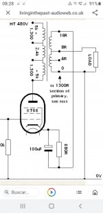
A trick for PP was also to ground the 4 Ohm tap, connect the two cathodes to the 0 and 16 Ohm tap, and connect the speaker as a standard.
A trick for PP was also to ground the 4 Ohm tap, connect the two cathodes to the 0 and 16 Ohm tap, and connect the speaker as a standard.
Local feedback around an output pentode can be sent to the cathode, screen grid, or control grid (usually to the plate of the driving tube). The UNSET topology takes Schade literally with a resistor directly between the plate and grid of the output tube with an additional resistor from grid to ground to create a voltage divider. The ratio of these resistors controls the "Mu" of the emulated triode. Drive signal is applied to the cathode via a transformer or P fet follower stood on its head.
"Schade" feedback does make pretty triode curves from most pentodes.
The feedback voltage divider can be separated into DC and AC components with a capacitor or two. The amp's output impedance (DF is inversely related to output impedance) can easily be measured by driving it to a safe level without a load, then loading it until its output drops to half voltage. At this point the amp's output impedance is equal to the load resistance. You can test the amp with several different feedback divider ratios. then play music with the same amp through your intended speakers and listen to the available choices for DF to see how much your speakers want.
As pointed out the DCR of both primary and secondary of the OPT reduce the DF, as does the DCR in your speaker wire. Measuring the output impedance of the amp at frequency extremes will reveal a few other imperfections that are usually from the OPT, but I have seen some changes in the low frequency range by swapping cathode bypass caps in the output stage if used.
This is a popular option on the Tubelab SSE board. It works wonders on undersized OPT's like those $29 Edcors. It doesn't do much for a large, good quality OPT unless your speakers need a lot of DF.In audio as well I’ve seen many circuits with cathode feedback only (using the secondary or a dedicated primary) or cathode feedback around 10% plus UL around 33%.
A trick for PP was also to ground the 4 Ohm tap, connect the two cathodes to the 0 and 16 Ohm tap, and connect the speaker as a standard.
I have a project of OTL with 6JN6's combining negative voltage feedback with adjustable positive current feeback. I robbed the idea from magzines and books. Really works pretty good.
Sounds like a great idea. Why don't you start a separate thread & tell us what tubes you intend to use & how many.I have a project of OTL with 6JN6's combining negative voltage feedback with adjustable positive current feeback. I robbed the idea from magzines and books. Really works pretty good.
Include a schematic & what kind of loudspeaker will work with your OTL. What kind of power supply, will it be. toobz or SS?
When it is up & running an account of the THD & IMD, not simply a comment that it sounds OK.
I'm sure we all could learn a lot from a full account of your experience with your project.
Looking forward to watch how your project progresses. 😀
👍
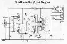
ARC used regulated fixed voltage screens, around 350DC, in their amplifiers with cathode feedback.This was done by Audio Research mainly but with UL stage
not sure

ARC used regulated fixed voltage screens, around 350DC, in their amplifiers with cathode feedback.
QUAD had a better solution. After some research they found the best degree of CFB that reduced 3H in PP pentode operation.A trick for PP was also to ground the 4 Ohm tap, connect the two cathodes to the 0 and 16 Ohm tap, and connect the speaker as a standard.
And a very simple but very effective driver stage, 😀
Attachments
This is a good starting point. However the Class A amplifier will always have the better damping factor. A Class AB2 amp is normally biased at significantly lower current where the plate resistance is somewhere between 20% and 100% higher, depending on the bias conditions. So, the transformer contribution might be less than 0.93R?In this exciting episode we will see how all power triodes have similar Damping Factors.
And how the Output Transformer will reduce that DF further.
Triode Damping Factor & Output Transformer Effect. John L Stewart Feb 2023
1) All Triodes Have Similar Damping Factors (DF)
In Class A the theoretical maximum output for common triodes occurs when the load impedance Rl is 2rp. In a practical circuit it is more like 2.5 rp. But distortion is rather high at that kind of load, a conservative designer might go for a 3rp or even 4rp load Rl.
Damping factor is simply the load impedance divided by the internal impedance of the amplifier. Taking the 2A3 & its specifications given in the RCA tube manuals we have-
At 250V on the plate & -45V on the grid rp of 800R & a recommended load of 2500R. That looks like a Damping Factor (DF) of 2500 / 800 or 3.13.
Another good example is the 10/10Y. In this case the plate is at 425V & the grid at -40. The DF looks like 10.2K / 5K or 2.04. On the low side, the spec is pushing for more power.
The 45 DF at 275V plate is 4600 / 1700 or 2.71.
In each case the DF could be improved by using a higher load resistance.
The signal still needs to get thru the output transformer. How much impedance the OPT will put in the way of the signal depends a lot on how much Gelt ($$$) people want to spend.
2) DF lowered by OPT
For an estimate of how much resistance an OPT adds to the internal impedance of an amplifier I ran these tests on the Class AB2 PP 6V6 experimental amp I built about 20 yrs ago.
Internal resistance for this was calculated by using the traditional Black Box method. With the signal applied & proper load connected the voltages are measured both Open Circuit (OC) & Closed Circuit (CC). And measurements ahead of the OPT on the plates & on the secondary. The primary side load used was 7K. The secondary 7.5R on taps 3-6, that reflects 6.8K to the plates. The internal impedance is (Eoc – Ecc ) / (Ecc/Rl ). And DF is Rl / Rint. Refer to the diagram.
Comparing the DF results on the OPT primary to the secondary of the OPT indicated the OPT was adding 0.93R to the output terminals.
JLS
Last edited:
The QUAD had the good solution (CFB) but, IMHO, it's all spoiled by GRND feedback. Pentodes (and tetrodes) that have at least (effective) 5 mA/V mutual conductance (like the EL34 used at 450-500V with 40 mA anode current + 400V for g2, outputting 60 to 75W with 5K p-p load with really low distortion) and used as such with 10% CFB already get a damping factor around 2.5. So this is possible even with class AB amps. If class A with almost 2xgm, higher plate load and CFB between 10-20% it can get really good.QUAD had a better solution. After some research they found the best degree of CFB that reduced 3H in PP pentode operation.
And a very simple but very effective driver stage, 😀
You can see that even the 811A with just 8dB CFB will get around 2 DF as measured by my friend Michi:
http://www6.plala.or.jp/Michi/811a24wseamp_0812.html
http://www6.plala.or.jp/Michi/811a24wseamp_0812.html
For starters I didn't say any of that. Go back, but read what I said carefully this time, 😀This is a good starting point. However the Class A amplifier will always have the better damping factor. A Class AB2 amp is normally biased at significantly lower current where the plate resistance is somewhere between 20% and 100% higher, depending on the bias conditions. So, the transformer contribution might be less than 0.93R?
Sorry, I just meant to say that as the Class AB2 amp is worse than Class A, one might get a better OPT with lower added resistance. The higher cost might be justified by higher output power. 0.93R is rather high on its own.
Last edited:
The circuit is actually working but it is in prototype state. Still remains unfinished. Unsure if sometime I'll finish it. I lost my job 3 years ago, and possibly you had listened in TV or radio that Argentina is becoming unlievable because corruption, delinquency and economy. Prices of good duplicates in a year while salaries are of misery (my apologies by the of topic but I need to explain this to justify why it is unconcluded).Include a schematic & what kind of loudspeaker will work with your OTL. What kind of power supply, will it be. toobz or SS?
It uses about 20 compactron tubes including rectifiers, no one grain of sand beyond the glass of them. I didn't do a schematic mediocrely showable, but I have an ASCII ART one. The positive current feedback is taken via a current transformer. The speaker is coupled via a toroidal autotransformer and the amplifier itself is fully DC coupled.
- Home
- Amplifiers
- Tubes / Valves
- Triodes Have Similar Damping Factors & How the Output Transformer Will Further Reduce That