If the throat is made smaller, the notch will shift upwards in frequency. The same goes for expanding bass horns and transmission lines (negative taper).
I wanted to do that but it doesn't work yet. Anyway, this is interesting and probably not quite intuitive.If you created a simulation with only a throat and one that included the conical portion of a compression driver would the 1/4 notch look the same?
It's not only a notch but also a directivity issue (based on the BEM sims), so for the best results it's probably better to avoid it. But maybe it's low enough level so it doesn't matter much.you can use the notch as part of the mid/high crossover in a synergy horn allowing the mid to go bit higher than expected.
And did you get it? 🙂 If so, could you explain it?I had the chance to ask Tom what distance from ports determines the notch, the throat or the CD diaphragm. He said the throat, and i asked why not the actual distance to the diaphragm. He said "think about it, all the pressure is going out".
No, i didn't get it then ....and still struggle with it now. Closest I've come is the idea that acoustic pressure flowing out the horn, moves some sort of pressure apex out into the horn.
Missed edit window...
One thing i do feel confident about, is that notch frequency is not determined by distance to CD diaphragm....
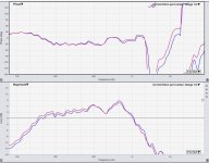
Here's raw response of mid ports on a 90x60 syn
where Red is with the CD mounted in place,
and Blue is with the CD off the horn.......so with mid ports reflecting to an empty hole. (1.4" CD hole)

Impulse ToF's were within 0.02ms. (1 sample at 48kHz)
One thing i do feel confident about, is that notch frequency is not determined by distance to CD diaphragm....
Here's raw response of mid ports on a 90x60 syn
where Red is with the CD mounted in place,
and Blue is with the CD off the horn.......so with mid ports reflecting to an empty hole. (1.4" CD hole)

Impulse ToF's were within 0.02ms. (1 sample at 48kHz)
Maybe the rear-traveling wave from the entry port doesn't "want" to get into the tiny bits inside the CD throat? Probably a better explanation involving impedance changes, diffraction etc. etc. but might be that sound is just "lazy".
Might be not far from truth - I would put it that once the dimension of the cross section is small enough (with respect to WL), the sound wave already reflects without "examining" further details of the apex. It's just that the details of the very end are no longer important - too small to matter.but might be that sound is just "lazy".
Last edited:
you could also consider the extreme case of 180 degree opening angle wherupon there will be no reflection.
Could it be that rapid change in cross section area cause diffraction, as in every discontinuity? Diffraction would be reflection in this case since the wave length is large compared to the diameter of the wg and the space is constrained.
This would explain why the notch gets higher than calculated. Same theory would apply inside a phase plug. Whether you get reflection or not from the face plug surface depends on how well the plug expansion match the throat and wg expansion.
This would explain why the notch gets higher than calculated. Same theory would apply inside a phase plug. Whether you get reflection or not from the face plug surface depends on how well the plug expansion match the throat and wg expansion.
Might be not far from truth - I would put it that once the dimension of the cross section is small enough (with respect to WL), the sound wave already reflects without "examining" further details of the apex. It's just that the details of the very end are no longer important - too small to matter.
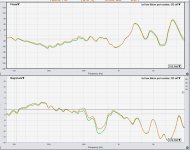
That idea has some intuitive appeal. It made me reexamine the same measurement I made on the low ports this morning.
Low ports are 7.5cm dia, and about 18.5cm from CD axially, 23cm from CD on horn walls. 10" drivers.
Green is with CD on; orange is with CD off.

Dunno what to think.
You mean off like removed? If so, it makes perfect sense.
Green curve has a deeper notch since the reflection is from both the somewhere in the driver and from the waveguide. In the orange case, the reflection only occurs from the change in expansion rate of the waveguide.
Green curve has a deeper notch since the reflection is from both the somewhere in the driver and from the waveguide. In the orange case, the reflection only occurs from the change in expansion rate of the waveguide.
ST260-alike, the same axial distance of the taps (40mm, surface sources only), three different throat diameters (12.7, 25.4 and 36 mm).


Vertical polars:


At first counter-intuitive, perhaps, but obviously real - the smaller the throat, the less time it takes the reflection (or whatever it is) to happen.
I'm tempted to try it with an open end but that would require some more coding and I'm as lazy as the sound, if not more at the moment...
Vertical polars:
At first counter-intuitive, perhaps, but obviously real - the smaller the throat, the less time it takes the reflection (or whatever it is) to happen.
I'm tempted to try it with an open end but that would require some more coding and I'm as lazy as the sound, if not more at the moment...
Last edited:
Yes, off as in CD totally removed. And I agree with what you say makes sense.You mean off like removed? If so, it makes perfect sense.
Green curve has a deeper notch since the reflection is from both the somewhere in the driver and from the waveguide. In the orange case, the reflection only occurs from the change in expansion rate of the waveguide.
When I said dunno what to think, it was in regards to the idea that when get wavelengths long enough relative to size of the apex, that that might define the location of an apparent reflective apex.
But the low ports are showing a difference around 700Hz, CD on vs CD off, that the mid ports don't.
Doesn't appear to support the idea.
I think it actually does support the idea, as only level changed, not frequency (if that's the notch).Doesn't appear to support the idea.
Ok, I guess i'm not understanding the idea as you presented. I thought it meant that when wl gets large relative to the size of the apex, the depth of the apex quits having an effect on the port to apex distance.I think it actually does support the idea, as only level changed, not frequency (if that's the notch).
But that's what I meant (I think).
Maybe an equivalent explanation would be the expansion rate (impedance rise), as mentioned before. It gets higher sooner as the throat gets smaller.
Maybe an equivalent explanation would be the expansion rate (impedance rise), as mentioned before. It gets higher sooner as the throat gets smaller.
Last edited:
Good. It's making more sense.
I realized i was making a mistake thinking there should of been some anomalies in the mid port test i made around 700Hz.....but my dumb **** forgot that the mid ports are too close to have any kind of notch there....lol
I realized i was making a mistake thinking there should of been some anomalies in the mid port test i made around 700Hz.....but my dumb **** forgot that the mid ports are too close to have any kind of notch there....lol
Could you fill the whole area between throat and midrange port with absorption? The compression driver only needs to pass it once and with a little eq it can compensate for the loss. But the midrange is traveling double the distance thru the absorption.The throat elements a) reflective and b) 100% absorptive:
View attachment 1142805View attachment 1142806 View attachment 1142807
This is of course something Mr Geddes know a lot more about, he even has a patent.
- Home
- Loudspeakers
- Multi-Way
- Acoustic Horn Design – The Easy Way (Ath4)