Hi guys,
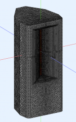
is there any possibility to have a MTM configuration in an infinite baffe without case? As mentioned before my mounting situation i in-wall so this might be best approximation.
I tried by just setting simtype to IB but thenn it does not compile. Assuming I have to change within this part:
Mesh.Enclosure = {
Spacing = 30,180,30,180 ; edge distances (left,top,right,bottom) [mm]
Depth = 200 ; enclosure depth [mm]
EdgeRadius = 20 ; radius of the edge treatment [mm]
EdgeType = 1 ; 1=rounded, 2=chamfered
FrontResolution = 8,8,16,16 ; front side mesh element size (q1,q2,q3,q4) [mm]
BackResolution = 20,20,20,20 ; back side mesh element size (q1,q2,q3,q4) [mm]
LFSource.A = {
Radius = 65
Spacing = 2
DrivingWeight = 1.0
SID = 1 ; 0 is reserved for the waveguide
}
I use quarter symmetry for that.
Thanks
If you have it generated in the layout you want with an enclosure, the cabinet elements can be removed or commented out in the solving file and replaced with an infinite baffle manually.
If you can't do it yourself post the project and I will show you how.
PS You will need interfaces between the woofers/waveguide and IB which can be tricky sometimes.
If you can't do it yourself post the project and I will show you how.
PS You will need interfaces between the woofers/waveguide and IB which can be tricky sometimes.
Hi
I can manage that in Akabak. Its easier then for me to just do the horn via ATH and add direct sound speakers in Akabak. But thanks 🙂
Would just have been easier for faster iterations if possible directly with ATH.
I can manage that in Akabak. Its easier then for me to just do the horn via ATH and add direct sound speakers in Akabak. But thanks 🙂
Would just have been easier for faster iterations if possible directly with ATH.
Current WIP. I'll be adding a woofer like @Olombo above. Then importing into Vituix to see what can be done about crossovers.


Do i need to attached a lem model for the 8pr200 ( in ath4 / lib / drivers ) to LFSource.A ?Crossovers are easy if model prepared with ath and then Akabak. Also linear phase since a while. Processing if solved once only few seconds for modified lem...
https://faitalpro.com/en/products/LF_Loudspeakers/product_details/datasheet.php?id=101030200
Need ton converter Rms Kg/s to Ns/m. I think I started this based on the 15PR400 from fluid.
Code:
//*****************************************************************************
//
// ABEC3 Lumped Element File
// Project:sealed woofer
//
//*****************************************************************************

// Thiele-Small parameter of electro-dynamic driver

Def_Driver '8PR200'      // 8 inch paper woofer
  Re=5.1ohm                    // datasheet
  Le=0.55mH                   // datasheet
  Mms=27.2g                   // datasheet
  Cms=0.28e-3m/N        // datasheet
  Bl=11.5Tm                     // datasheet
  Qes=0.38                     // datasheet
  Qms=9.4                      // datasheet
  Rms=3.11Ns/m             // ??? use HornResp to derived
  Fs=58Hz                      // datasheet
  // SD=209cm2             // datasheet
  // fre=3.1kHz                //
  // ExpoRe=0.824         //
  ExpoLe=0.3                 //

Def_Driving "Driving"
  DrvValue=2.83V        // assumption is gnd=node "0" and output is node="1"
  IsRms

// Lumped element network
System 'Woofer'
    //Filter 'WooferLR4LP' f0=700Hz V0=1 Order=4 LR Lowpass;        // implicit input
    Driver  'Drv1'
    Def='8PR200'
    Node=2=0=111=112                  // connected woofer to LP filter, lowest node is input
    // DrvGroup=1011,1012             // front,rear of woofer 2 port
    DrvGroup=1011                         // front only,
      RadImp 'WooferFront'            // rad imped,  a different object
    Node=111                                  // connect drive source node
    DrvGroup=1011                         // the DrvGroup links the LE to BE
    // RadImp 'WooferRear'            // rad imped, a different object
    // Node=112
    // DrvGroup=1012
    Enclosure "WooferRearChamber"        // using a lumped compliance model with damping
    Node=112                  // connect to drive source node
    Vb=20L                     // rear chamber volume
    // Lb=10cm                // rear chamber length
etaB=2.7e-2 // medium damping@mabat
Can you check to see if my_plan meshes when using LFSource - Ath 4.9.0-pre-230113
Can you check to see if my_plan meshes when using LFSource - Ath 4.9.0-pre-230113
Code:
Mesh.Enclosure = {
  Plan = my_plan
  Spacing = 5,40,5,270
  FrontResolution = 8,8,14,14
  BackResolution = 25,25,25,25
  LFSource.B = {
    Radius = 85
    Spacing = 5
    DrivingWeight = 1.0
    SID = 1                ; 0 is reserved for the waveguide
  }
}

my_plan = {
  point  P0 125 0 8
  cpoint C1 125 25.0
  point  P1 149 17.8 8
  point  P2 160 90 14
  point  P3 130 225 25
  point  P4 40 350 25
  point  PB 0 350 25
  arc P0 C1 P1
  line P1 P2
  line P2 P3
  line P3 P4
  line P4 PB
}- There was quite a demand for this, I'm slowly working on. There are still some questions to be answered 🙂


First quick comparison, without and with the MEH ports (HF section only, horizontal polars, horn free standing as shown).


Yes!
mabat, thank you for this. I've been waiting eagerly to see the addition of multiple entry ports for a long time and this is no doubt someting that has been highly anticipated by many here
mabat, thank you for this. I've been waiting eagerly to see the addition of multiple entry ports for a long time and this is no doubt someting that has been highly anticipated by many here
Would a small radius edge around the port openings inside the horn make any difference in the simulation?
I don't know, that would be already quite a small detail for a model, I most probably won't include that.
- The above "cyl2" with a linear abscissa, 40 points. Probably good enough already, hard to say 🙂
(There's an added wall damping for the chamber+port elements, Damping=0.1 currently, I haven't tried its effect yet.)

- The above "cyl2" with a linear abscissa, 40 points. Probably good enough already, hard to say 🙂
(There's an added wall damping for the chamber+port elements, Damping=0.1 currently, I haven't tried its effect yet.)
No damping (left) and Damping=0.1 (right) inside the chamber and the port. It probably makes the results more realistic overall. Or do people see such things in real MEH constructions? (This is still only the HF section driven.)


I think it does make the result more realistic to add damping, as the no damping results are just not true to life. The worst aspects are accentuated. Round is worse too. Seen in my simulations of much the same without any damping added. A test build would be useful to identify a level of damping that gives the most realistic result.
https://www.diyaudio.com/community/...aker-build-abec-modelling.357792/post-6539838
https://www.diyaudio.com/community/...aker-build-abec-modelling.357792/post-6539838
- Home
- Loudspeakers
- Multi-Way
- Acoustic Horn Design – The Easy Way (Ath4)