CCS for JFets ....... use whatever you have
I certainly would not use P-JFET family like J174, J175, etc.
Just check noise figures.
Just me,
Patrick
thanks @Nelson Pass , I think I have a small sealed bag of 20pcs of j113. I will pull it out today and take a look.
I also have a bag of 113’s, just chime if you want them sent. IDSS from 13-20mA I believe, with some variation.thanks @Nelson Pass , I think I have a small sealed bag of 20pcs of j113. I will pull it out today and take a look.
Hugz

Thanks @andynor
I have j310 smd and not 113, actually I have a few types of jfets but all are smd. mmbf5486, j310, 2sk2145, 2sk209, bf862.
What is the difference if you use a highly degenenerated high idss jfet in a ccs vs a low idss not degenered one?
With a few(2-3pcs) paralleled and degenerated 2145bl I could get easily to 10ma if there is no difference between degeneration and no degeneration in a ccs like here.
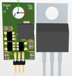
It happens that recently I took ZM idea of paralleling multiple 2145 and put it on an aluminum pcb, though I didn’t order yet the pcb. It has k170 pinout and to220 size.
If high degeneration is desirable in a jfet ccs means that this design could work here also, thing that I will try in my j2.
If high degeneration is desirable in a jfet ccs means that this design could work here also, thing that I will try in my j2.
Attachments
Electronics design has a nice article on this, bonus points (at least in my book) that it’s written in a style reminiscent of Bob Pease’s old ED articles (it even references one). If you follow the link, click on the download button towards the bottom of the page for the pdf of the article:
https://www.electronicdesign.com/po...fet-constantcurrent-stuff-anyhow-pdf-download
Alternatively here’s the direct link to the pdf (not sure if this will work):
https://cdn.baseplatform.io/files/b...05/electronicdesign_26950_what_s_all_this.pdf
https://www.electronicdesign.com/po...fet-constantcurrent-stuff-anyhow-pdf-download
Alternatively here’s the direct link to the pdf (not sure if this will work):
https://cdn.baseplatform.io/files/b...05/electronicdesign_26950_what_s_all_this.pdf
Which is the best practice to solder J113 in pin hole pattern for 2SK170? Or is there a pin compatible alternative?Just use J111 112 113. Works like glue, holds 70v in tests.
IF you use the amplifier with single ended input, i.e. -Vin = 0V, then R3 should be 10k, R4 should be 100k.
IF however you are using symmetrical inputs, i.e. -Vin = -(+Vin), then those value as published will load the source symmetrically.
You can figure this out by running the Spice files published before, and look at current amplitudes through R1 and R3.
Those spice files are using symmetrical inputs, as I would.
If I use symmetrical XLR inputs (with the original values for R3 and R4 below), can I still use the single-ended RCA inputs by using a jumper between pins 1 and 3 of the XLR connector as stated in the J2 owner manual?
Thanks!
And since I still do not have the parts with me, I shall use EUVL Spice file and play with values.
Speaking of which, if I replace Q4 with a IRFP240 or add parallel Q1-Q2-Q3 in the front end, should I consider changing any other value in the EUVL schematic above?
And since I still do not have the parts with me, I shall use EUVL Spice file and play with values.
Speaking of which, if I replace Q4 with a IRFP240 or add parallel Q1-Q2-Q3 in the front end, should I consider changing any other value in the EUVL schematic above?
- Home
- Amplifiers
- Pass Labs
- FirstWatt J2