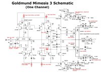
I added a 30pf on each of my lateral mosfet outputs on another amp, as this was an update made to the later designs. I didn’t have any problems with that amp, and those parts were added with other changes, so I can’t tell if they contributed to any sonic improvements on their own,
My headphone amp, however, had been prone to a buzzing from some interference and the same parts, from gate to drain, has cleared it up. Silver mica, or polystyrene preferably.
My headphone amp, however, had been prone to a buzzing from some interference and the same parts, from gate to drain, has cleared it up. Silver mica, or polystyrene preferably.
There is no cable attached to the input. Just the shorted terminals. It has 20 mV and it is measured at the speaker output. Matches the picture from my previous posts.
I would like to eliminate it.
20mv AC or 20mv DC?
If DC , you can adjust R8 pot.
If AC ,(it's a little difficult) you must start ;remove 8,2pf capacitors,cut legs and re-soldered.
Thank you caglarm.
DC offset works fine, this AC mounted over DC.
I will try your advice and report about 10 pF capacitors.
DC offset works fine, this AC mounted over DC.
I will try your advice and report about 10 pF capacitors.

I thought, I'll try to create it, but it's hard to do and very expensive and time-consuming, persevering.Where are the latest gerbers files final version and tested ok ?
Because before, I drew the pcb completely by hand, without the schematic diagram, so listing the components took a lot of time. I'll try
Hello friend!I thought, I'll try to create it, but it's hard to do and very expensive and time-consuming, persevering.
Because before, I drew the pcb completely by hand, without the schematic diagram, so listing the components took a lot of time. I'll try
You consider Goldmund. the best?
You have me as a client, if you're interested.
I'd like a couple of finished boards with components.
But I can't find conditions to mount im, there's no support here on the forum.12 year have gone ,,, still the best???
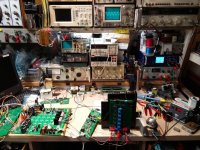
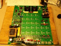
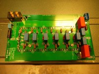
Top board is the full input and driver sections, and also holds the voltage doubler.
I hope it is as good as you're saying. I have a pair of Telos 2500 monoblocks in the making 😉 I have also the digital input PCB dac with PCM1794 Dac chip. I used an Arduino processor and did the code myself.
SB
SB
Attachments
-
 IMG_20210314_165250.jpg456.3 KB · Views: 321
 -
 IMG_20210521_113901.jpg267.5 KB · Views: 324
 -
 Prototype PSU PCB Testing.jpg277.3 KB · Views: 328
 -
 Input Card Prototype Testing.jpg241.3 KB · Views: 335
 -
 IMG_20210520_203613.jpg135.5 KB · Views: 323
 -
 IMG_20210316_101836.jpg461 KB · Views: 329
 -
 FAV Prototype working.jpg346.5 KB · Views: 297
 -
 FAV PCB Mods.jpg373.2 KB · Views: 302
Hi Guy's.
Good to see your building high quality amplifiers. If haven't already seen it you may want to check out the wolverine amplifier it also has super low distortion.
We have some PCB'S available if anyone would like to build one.
Wolverine project
Good to see your building high quality amplifiers. If haven't already seen it you may want to check out the wolverine amplifier it also has super low distortion.
We have some PCB'S available if anyone would like to build one.
Wolverine project
- Home
- Amplifiers
- Solid State
- The Very Best Amplifier I Have Ever Heard!!!!