With good guesses the optimization will converge quicklyJack informed me that Lipshitz's figure 3 is essentially a standard non-inverting RIAA circuit. As the gain is an impedance ratio plus one, or more generally plus some constant, the gain fails to drop to zero when the frequency approaches infinity.
If I understand it correctly, Lipshitz just places the RIAA correction poles and zeros at their ideal locations and then gets an error due to the extra zero caused by the + 1 term (and explains how to get rid of it with an extra first-order filter, if desired), while Ellis tweaks the RIAA correction poles and zeros to more or less compensate for the effect of the + 1 over the audio band.

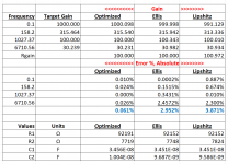
Here's a chart which illustrates the difference, using the "Ellis" values from the AudioXpress article, then using R1 of 92.152k Ohm as a seed value for the "Lipshitz" values. Gain error is adjusted to 0dB @1kHz. In both cases, R(0) = 100 Ohms.
I don't understand the Lipshitz graph.
Lipshitz puts the RIAA correction poles and zeros at the desired locations and then gets an extra ultrasonic zero due to the constant +1 term. If a high pass is included, like the former IEC 7.95 ms first-order high-pass, there is an extra error at low frequencies due to the zero of the high-pass being shifted out of the origin, again due to the +1 term.
The error is about +0.04 dB at 20 kHz, corresponding to a zero with a corner frequency of about 208 kHz (that is, zero position about -416 pi krad/s). That means that the midband gain must be about 100 and the low frequency (20 Hz to 50 Hz) gain around 1000. The low-frequency zero then has a corner frequency of about 20 Hz/1000 = 20 mHz, that is, the zero shifts from the origin to about -40 pi mrad/s due to the +1 term.
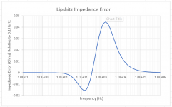
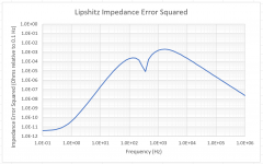
When I calculate the effect of a zero at -40 pi mrad/s that should have been at 0 and a zero at -416 pi krad/s that shouldn't have been there at all (or should have been at infinity), I get this:
which doesn't resemble the blue graph of post #58 much, at least not below 3 kHz. Does Ellis account for other imperfections as well, besides the +1 term?
Last edited:
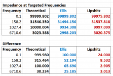
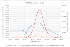
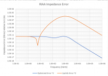
Perhaps this explains the error. I used the Laplace transforms to calculate the impedance of the Lipshitz and Ellis RC networks compared with the scaled impedance using T3,T4 and T5 for Ellis' frequencies.
The gain for Ellis is then ~= 1+(99.899kΩ/100Ω) = 1,000 at 0.1Hz and ~= 100.3@ 1,027.37 Hz
So, using the theoretical network impedance, subtract the resistance of the gain resistor and solve.
The gain for Ellis is then ~= 1+(99.899kΩ/100Ω) = 1,000 at 0.1Hz and ~= 100.3@ 1,027.37 Hz
So, using the theoretical network impedance, subtract the resistance of the gain resistor and solve.
Attachments
What's so terrible about using crappy guesses? What's so terrible about using a tremendously robust but "slow" global optimization algorithm? Why not deploy Genetic Algorithm or even Simulated Annealing? They deal with multimodal objective space quite handily.With good guesses the optimization will converge quickly
Set all resistors to 1K and set all capacitors to 22nF then hit Go. Watch an episode or two of The Great British Baking Show, an episode or two of Barnaby Jones, and trundle off to sleep. Retrieve the global optimum network values after morning coffee.
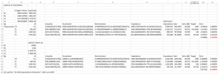
Since there are only 4 frequencies to examine, rather than an optimization I chose the "eyeball" method, first adjusting the value of R2, then C2, slightly tweaking the value of R1. That's a "hat tip" to Mark.
The matrix just uses the complex math functions of Excel and rather than writing one long expression divides the job into numerator and denominator.
The matrix just uses the complex math functions of Excel and rather than writing one long expression divides the job into numerator and denominator.
Attachments
Hypothetically suppose the optimization procedure calculated magnitude and magnitude_error at N frequencies rather than 4 frequencies. (N > 4)
If you increase the number of frequencies by a factor of three, does the optimization run-time increase by a factor of 3^2 (9x)? Does it increase by only a factor of three? Less than three?
Suppose you ran the optimization across N frequencies, for every integer N from 4 to 20. Suppose you plotted the post-optimization gain error ((1/N) * SUM(Abs_error)) versus N. Does the post-optimization gain error get better and better as you increase N more and more? Is there a "best" value of N which gives better post-optimization gain error than any other N?
There seems to be a very simple rule in all of this, use a value of C2 about 5% higher than specified by L.
For practical purposes, I have resistors matched to the specified values with an HP3456A and Kelvin clips which will do a milli-Ohm, and capacitors selected to the values using my Omicron network analyzer to about a pF. It's really tough and probably not worth a fraction of an ounce of a mare's sweat (you have to have seen "A Funny Thing Happened on the Way to the Forum") to aim for this precision. As an academic exercise, however, ever the pedant!
For practical purposes, I have resistors matched to the specified values with an HP3456A and Kelvin clips which will do a milli-Ohm, and capacitors selected to the values using my Omicron network analyzer to about a pF. It's really tough and probably not worth a fraction of an ounce of a mare's sweat (you have to have seen "A Funny Thing Happened on the Way to the Forum") to aim for this precision. As an academic exercise, however, ever the pedant!
I have a Pass Pearl II that has MilMax female headers to try an assortment of resistor and cap values (Pearl uses the passive Lipshitz "1C" configuration). At the spot frequencies I was able to run, the Lipshitz values are superior to the "Optimized" values, disrespecting all of those Laplace transforms in Excel. Will have to try this in the active "1A" configuration.
Attachments
An extension of this -- will probably have to start a new thread -- I took the Laplace using the time values (t3, t4, t5) , and the Laplace using RC values carried out to 5 digits. In addition, I used multiple decade frequencies. If running an Excel I minimize to the sum of squared errors.
Attachments
Here's another example of optimization. Note that Lipshitz in his 1977 article said his work was accurate to a tenth of a dB. This optimization is a wee bit better. Original values R1 120k, R2 10k, C1 26.5n, C2 7.5n. Optimized values R1 120k, R2 10.170k, C1 26.5n, C2 7.36n. I am away from the workshop, so won't be able to demonstrate "reality" until next week:
Log Squashed Error is ABS(LN(1-ABS(ERROR))). Optimize for the minimum.
Log Squashed Error is ABS(LN(1-ABS(ERROR))). Optimize for the minimum.
Attachments
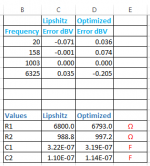
The differences in impedance between the Lipshitz values and those optimized, are the difference between a milli-Ohm and a micro-Ohm. Given that my HP3456A will only get to 1 milli-Ohm at DC I would say the results are pretty much inconsequential. Even with the VNA you are going to see some reactive impedance for the best of components!
Interesting, R1 * C1 still gives 3180us, and R2 * C2 gives 75 us, but (R1 || R2) * (C1 || C2) shifts from 318.000 us to 318.083 us
Interesting, R1 * C1 still gives 3180us, and R2 * C2 gives 75 us, but (R1 || R2) * (C1 || C2) shifts from 318.000 us to 318.083 us
Attachments
- Home
- Design & Build
- Software Tools
- Using the Jacobian matrix and Excel/Matlab to solve for RIAA network values