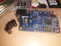
Input from what source device?I am considering to get a AK4113 input board with a display. Just to be sure:
- from this thread I grasp this board is compatible with the AD1862. Is that correct?
- the AK4113 can do up to 192 kHz, and is already somewhat older. Is there a more up to date alternative ready made input board available?
It should work, if you check the page 30 in datasheet, mode 5 is I2S output with 64fs and this works ... be sure your desired device has this mode implemented 😊
Thanks for replying.
I already have a recent JLSounds USBtoI2S with separate clock board. So, that should work directly into the AD1862 board (which I am currently building with PSU-2).
However, I would like to add another digital source. Preferably also via I2S from my reclocked RPi 3B for streaming. Or maybe even via SPDif from the CD-player or other digital source. So, actually what is required is a decent switch that does not degrade the available USB input source. It looks like the AK4113 is suitable; I will have a look at page 30 of the datasheet.
Here's what the creator of this PCM1702/PCM63 adapter probably did, I will check it out later. He put these three electrolytic capacitors on the adapter PCB according to the datasheet (22uF+47uF+100uF). The other four decoupling capacitors on digital and analog +-5V supplies are on the Miro PCB (100uF along with parallel 100nF PP).poor PCM1702s😢
one PCM1702 needs 7 electrolytes from 47uF to 100uF, 4 for decoupling and 3 of better quality with a small leakage current for internal references
All the ones I got were LOW ESR, Panasonic, NIC and the like from local stores. I don't see any problem, that should work nicely instead of PCM63 on the Miro DAC board.
I don't know if it would be wise to put some small ones of 100nF on the adapter PCB in parallel with these three electrolytic capacitors? I have a lot of 100nF ceramic 1206 SMD and Wima MKS2?
Attachments
Last edited:
Small correction: 2x47uF digital part, 2x100uF analog part of the PCM63(100uF along with parallel 100nF PP).
I only know about this model. The I2S input is used for I2S output from the JLS board and I haven't noticed it affecting the sound so far. To the AD1862/1865/PCM63 and similar, the I2S output signal will go either from the AK4113 chip or from the JLS board, selected with one button.I am considering to get a AK4113 input board with a display. Just to be sure:
- from this thread I grasp this board is compatible with the AD1862. Is that correct?
- the AK4113 can do up to 192 kHz, and is already somewhat older. Is there a more up to date alternative ready made input board available?
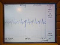
It was tried with the Pavouk AD1865 DAC and board passed 384kHz 24bit from the JLS, it worked but there was some metallic undertone. I guess the problem was either in the AD1865 or my PC. 192kHz 24bit is more than enough for me, and most recordings are 44.1khz 16bit anyway.
https://www.ebay.com/itm/124527230196?mkevt=1&mkpid=0&emsid=e11051.m43.l1123&mkcid=26&ch=osgood&euid=6d354a83d8fe45378fca145127ba3c19&bu=44456828498&osub=-1~1&crd=20221014025847&segname=11051
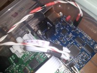
Delighted to hear that Vunce!Getting my pair of FC CEN I/V boards built, adjusted and mated to my AD1862 DAC took a bit longer than I anticipated with the holiday break. But, today we have music! All seems to be working smoothly so far. Patience has paid off with this project as my DC offset is stable and less than 1mV(both channels).
Thank you to Patrick for sharing your creation and build support, Fran your amazing build guide and Miro’s DAC platform.

I like how you mounted them as well - its a neat footprint.

How hot is the stabilizer for the XMOS part of the JLS board? I bet you need a bigger cooler there.All seems to be working smoothly so far.
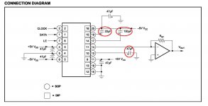
Unfortunately, the person who made the adapters did not read the DS until the end where it says ; As shown in CONNECTION DIAGRAM, various sizeHere's what the creator of this PCM1702/PCM63 adapter probably did, I will check it out later. He put these three electrolytic capacitors on the adapter PCB according to the datasheet (22uF+47uF+100uF). The other four decoupling capacitors on digital and analog +-5V supplies are on the Miro PCB (100uF along with parallel 100nF PP).
All the ones I got were LOW ESR, Panasonic, NIC and the like from local stores. I don't see any problem, that should work nicely instead of PCM63 on the Miro DAC board.
I don't know if it would be wise to put some small ones of 100nF on the adapter PCB in parallel with these three electrolytic capacitors? I have a lot of 100nF ceramic 1206 SMD and Wima MKS2?
decoupling capacitors can be used, with no special tolerances being required. The size of the offset decoupling capacitor is not critical either, with larger values (up to 100μF) giving slightly better SNR readings. All capacitors should be as close to the appropriate pins of the PCM1702 as possible to reduce noise pickup from surrounding circuitry.
It would be better if you put that 100nF SMD right on the power supply pins on the adapter itself, because the PCM1702 produces interference at some 3.6MHz. COG SMD would be better with these frequencies. Avoid PP or MKS2 because of the long legs, especially since here the PCM1702 is on the adapter and it is not very close to the decoupling capacitors. Panasonic FC would be a good choice for all 7 capacitors , 100uF/25V also has a small leakage current..
Attachments
A couple of days listening to AD1862 with FC CEN I/V and the sound is very impressive! I rarely talk about subjective sound quality as its personal to you and your own system, but I can say over the past few years playing around with many different types of I/V output stages with MiroDac the CEN is at the top of the list. If there is an open GB for these boards, Just go for it!
Well done Patrick👍🏻
Well done Patrick👍🏻
The BD139 NPN does get hot (50°C) with that small slide on heatsink but no where near its maximum 150°C temperature. Having built many Class A room heater amplifiers this is nothin’🤣How hot is the stabilizer for the XMOS part of the JLS board? I bet you need a bigger cooler there.
I know that about BD139, I will change that soon. I asked about the external stabilizer that powers the JLS board. I see there is a small cooler in your pictures.
I'm just interested in getting the PCM1702 working on the Miro board for the PCM63 and hearing what the differences are. Considering that PCM63 chips are running out, PCM1702 can be a good alternative, there are still many available and they are not expensive. And if someone wants a good and cheap DIY DAC, he can get it with JLS board, AK4113 board, Miro PCM63 board with PCM1702 and some cheaper power supplies.Unfortunately, the person who made the adapters did not read the DS until the end where it says ; As shown in CONNECTION DIAGRAM, various size
decoupling capacitors can be used, with no special tolerances being required. The size of the offset decoupling capacitor is not critical either, with larger values (up to 100μF) giving slightly better SNR readings. All capacitors should be as close to the appropriate pins of the PCM1702 as possible to reduce noise pickup from surrounding circuitry.
The fact that it will be a little better S/N if I put all capacitors on the adapter 100uF is not so important, I can always change them.
In the datasheet, paragraph before that, it says that you don't have to separate the power supply for the analog and digital part of the chip, which I don't think is very good, it's just cheaper.
Last edited:
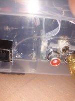
you are all addict to those red mushrooms... risking sounding halucinations ! (ok, keep me two !)
Unfortunately, all capacitors must go on the underside of the PCB. Otherwise, it is difficult to change operational amplifiers and DAC chips. Let's say the adapter for PCM1702 is 20mm wide and all the parts around it get in the way. I mean functionally there is no difference, it's just uglier when you can't see the beautiful parts. The electrolytic capacitors will be Elna Silmic II and Nichicon Gold on the PCM63 boar. For the AD1865 board I chose NIC and Panasonic LOW ESR capacitors. Wima PP are definitely red. 🤣
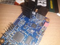
I replaced the heatsink on the JLS board (on the BD139 transistor). The combination of a 4VDC power supply and a slightly larger heatsink gives a slightly lower temperature. One cooler rib can be shortened by 2-3 mm so that it does not touch the spacer or the nut. Isolator is silicone washer. The original heatsink does not have thermal paste or good contact, which means that we do not know the temperature of the transistor. Now it is safe.
Attachments
It's not so important to separate those power supplies, Burr Brown didn't separate them in his best DAC evaluation module, just like Krell, Wadia didn't separate them ... there's no need to play bigger faces than those in BB.I'm just interested in getting the PCM1702 working on the Miro board for the PCM63 and hearing what the differences are. .......
In the datasheet, paragraph before that, it says that you don't have to separate the power supply for the analog and digital part of the chip, which I don't think is very good, it's just cheaper.
But BB put a digital isolator between the filter and the PCM1702, we need to think about that. I ordered some and they are waiting for the test, but I am worried about their jitter.
Attachments
I have no intention of ever using a digital filter. So I started with the DDDAC and continued with these Miro DACs. Just NOS DAC, nothing else.But BB put a digital isolator between the filter and the PCM1702, we need to think about that. I ordered some and they are waiting for the test, but I am worried about their jitter.
Got my 1541 boards here and realising what a good PCB PSU1 for TDA1541 is. Very handy. Gives us 3 x bipolar supplies if we consider IC1 and IC4 as a dual pair. Could even cut down between IC4 and IC5 if wishing to split the boards supplies.
Could also provide us a seperate bipolar for AD1862 opamps. Or usual 2 supply set up and then use IC1 for your digital front end!
Brill. Thanks Miro
Could also provide us a seperate bipolar for AD1862 opamps. Or usual 2 supply set up and then use IC1 for your digital front end!
Brill. Thanks Miro
- Home
- Source & Line
- Digital Line Level
- DAC AD1862: Almost THT, I2S input, NOS, R-2R