Those other data can be easely find:I did some standards measurements using a Rhode & Schwarz $50,000 Vector Network Analyzer and $10,000 Precision Short, Open, and Load Calibration kit. I had various interstage and output transformers that I measured.
Measurements included primary impedance and phase angle versus frequency; secondary impedance and phase angle versus frequency; primary resonance; primary to secondary leakage reactance, primary to secondary phase versus frequency; primary distributed capacitance; insertion loss versus frequency; several types of measurements with loaded secondary, shorted secondary, and with open secondary.
I also measured square wave response.
And I made some very accurate DCR measurements on those transformers too.
Then the data was recorded and analyzed further.
I can not remember if I made more measurements beyond what I listed above.
When I talked about the copper losses on these threads, the total loss I listed was only the copper losses.
Thanks for telling me that my posts in this thread were not about copper losses.
(I am actually aware of some other losses: laminations, coupling factors, fields that were beyond the windings and laminations, etc).
Perhaps I need to find some of those other manufacturers test methods, test equipment manufacturers and model numbers, and the test methods and practices that they followed.
Then I will look at their research, and see where I made all those mistakes in making the measurements and calculations on the many transformers that I had and measured.
-http://www.monolithmagnetics.com/products, for instance http://www.monolithmagnetics.com/sites/default/files/datasheets/Single-ended-output-transformers/datasheet S-9 300B single ended output transformer prelim.pdf
Or Lundahl, a popular transformer is this one http://www.lundahl.se/wp-content/uploads/datasheets/1620_3_7_9202.pdf
I think you are a capable guy with great measurement equipment, now it’s time to use the test methode all others do😉 (so we can compare the results)
Btw skip you own methode because your methode is AC methode, not DC.
Last edited:
tubes4all,
Thanks for those data sheets.
I will have to do the calculations based on the specifications in those data sheets, when I get caught up on other things.
I have seen other models data sheets from both those manufacturers.
And I have used a couple of different Lundahl interstage transformer models.
I measured one Lundahl, but I did not have access to the Rohde & Schwarz VNA when I had the other model of Lundahl interstage.
As to the measurement methods, none of those data sheets show the measurement methods and setups.
Yes, those are excellent companies; but without any documentation of their test setups, I can wonder how they did their testing.
Simple, only dc measurements, otherwise you also measure the core and then hell will open.tubes4all,
Thanks for those data sheets.
I will have to do the calculations based on the specifications in those data sheets, when I get caught up on other things.
I have seen other models data sheets from both those manufacturers.
And I have used a couple of different Lundahl interstage transformer models.
I measured one Lundahl, but I did not have access to the Rohde & Schwarz VNA when I had the other model of Lundahl interstage.
As to the measurement methods, none of those data sheets show the measurement methods and setups.
Yes, those are excellent companies; but without any documentation of their test setups, I can wonder how they did their testing.
If you want AC measurements try this: impedance
tubes4all,
Thanks for those data sheets.
I will have to do the calculations based on the specifications in those data sheets, when I get caught up on other things.
I have seen other models data sheets from both those manufacturers.
And I have used a couple of different Lundahl interstage transformer models.
I measured one Lundahl, but I did not have access to the Rohde & Schwarz VNA when I had the other model of Lundahl interstage.
As to the measurement methods, none of those data sheets show the measurement methods and setups.
Yes, those are excellent companies; but without any documentation of their test setups, I can wonder how they did their testing.
Hi
I think if you use LIMP from Arta you can have a good results.
https://artalabs.hr/support.htm from page 28
Also with Rew
You need a good sound card.
As I shown some time with a specific sw (not available at the moment, sorry but I am pushing my friend to relase it) you can see all
Attachments
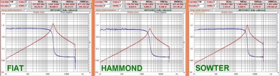
Can you explane why the data in the graph is not matching with the graph itself?Hi
I think if you use LIMP from Arta you can have a good results.
https://artalabs.hr/support.htm from page 28
Also with Rew
You need a good sound card.
As I shown some time with a specific sw (not available at the moment, sorry but I am pushing my friend to relase it) you can see all
I want to clear up the limited scope of what I am talking about in this thread:
Measure a few specific characteristics of a vacuum tube SE or PP output transformer.
Then, based on those few fundamental measurements, be able to calculate the absolute minimum amount of insertion loss at 1kHz (midband).
It can be larger than that minimum, because it only includes one cause of insertion loss.
But it can not be less than the minimum, or we have "perpetual motion".
The accurate electric measurements of turns ratio, the primary DCR and secondary DCR, are all you need to be able to calculate the absolute minimum insertion loss; of course there are additional loss factors, so the total insertion loss will be more than that calculated minimum.
Measurement method: perhaps I will write that up later.
That is kind of like calculating that a car can go at least a minimum of 80 MPH, but finding other factors that can make it go much faster: 120 MPH.
Is that clear?
It would be clear if you defined what you want to measure and why and the how.I want to clear up the limited scope of what I am talking about in this thread:
Measure a few specific characteristics of a vacuum tube SE or PP output transformer.
Then, based on those few fundamental measurements, be able to calculate the absolute minimum amount of insertion loss at 1kHz (midband).
It can be larger than that minimum, because it only includes one cause of insertion loss.
But it can not be less than the minimum, or we have "perpetual motion".
The accurate electric measurements of turns ratio, the primary DCR and secondary DCR, are all you need to be able to calculate the absolute minimum insertion loss; of course there are additional loss factors, so the total insertion loss will be more than that calculated minimum.
Measurement method: perhaps I will write that up later.
That is kind of like calculating that a car can go at least a minimum of 80 MPH, but finding other factors that can make it go much faster: 120 MPH.
Is that clear?
There was a thread on diyaudio here where someone wanted to measure the distortion of a transformer but didn't understand that that's a function of the impedance of the source. We not need such thing again i guess.
- Home
- Amplifiers
- Tubes / Valves
- Frequency response. Is bigger range better?