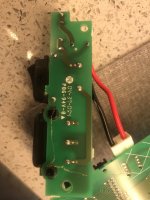
Hi I have a Bose lifestyle pa18-48, which was given to me only problem is that it’s 110v and here in Uk it’s 240v. Is there a way to do this with the existing transformer? There is a wire in between the transformer, I’ll add some photos thank you
Attachments

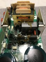
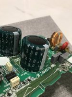
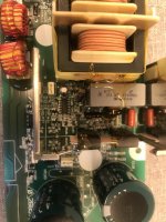
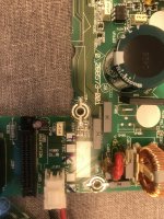
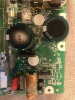
It is an SMPS that almost sure runs on any voltage from 90 to 240. Which are the values of that bulky filter capacitor (large black plastic-covered cans)?
Hi thank you for your reply they are 250v 470uf will add photoIt is an SMPS that almost sure runs on any voltage from 90 to 240. Which are the values of that bulky filter capacitor (large black plastic-covered cans)?
Attachments
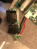
Well. Try to measure if one of the line input traks goes to the junction of both caps in series. Cut this track 1 or 2 mm wide. Go for a series lamp (filament), no CCFL nor led nor Fluoro. 50 to 100W is sufficient. Remove the fuse and wire the lamp with its socket and a couple of short pieces of wires to the fuse holder. Energize the PSU alone. You will see a flash on the lamp followed by a dark filament. Measure output voltages. If and only if they are OK and the lamp is dark, the SMPS is ready for 240V. If the lamp remains red, something is wrong and re-check.
Edit: both input line wires must go to the diode bridge and small capacitors and inductors of the line filter but not to the large 470uF/250V.
Edit: both input line wires must go to the diode bridge and small capacitors and inductors of the line filter but not to the large 470uF/250V.
Last edited:
Well. Try to measure if one of the line input traks goes to the junction of both caps in series. Cut this track 1 or 2 mm wide. Go for a series lamp (filament), no CCFL nor led nor Fluoro. 50 to 100W is sufficient. Remove the fuse and wire the lamp with its socket and a couple of short pieces of wires to the fuse holder. Energize the PSU alone. You will see a flash on the lamp followed by a dark filament. Measure output voltages. If and only if they are OK and the lamp is dark, the SMPS is ready for 240V. If the lamp remains red, something is wrong and re-chech.
Thank you for your reply, will give this a try and get back to you, 🙏🏼Well. Try to measure if one of the line input traks goes to the junction of both caps in series. Cut this track 1 or 2 mm wide. Go for a series lamp (filament), no CCFL nor led nor Fluoro. 50 to 100W is sufficient. Remove the fuse and wire the lamp with its socket and a couple of short pieces of wires to the fuse holder. Energize the PSU alone. You will see a flash on the lamp followed by a dark filament. Measure output voltages. If and only if they are OK and the lamp is dark, the SMPS is ready for 240V. If the lamp remains red, something is wrong and re-check.
Edit: both input line wires must go to the diode bridge and small capacitors and inductors of the line filter but not to the large 470uF/250V.
Ok. Keep the track that join both caps in
series as original. Only cut the track (or may be a wire or jump that enables it to work on 110 or 220VAC) that interconnects both caps to one line wire.
series as original. Only cut the track (or may be a wire or jump that enables it to work on 110 or 220VAC) that interconnects both caps to one line wire.


Some notes adding to Osvaldo's solution:
A connector with jumpers have been used in the past, shifting from low to high voltages by reversing it.
The drawn resistors in #7 should be of a robust power rating. They're splitting the rectified line voltage (240 * √2 = 336, but do include line variation also!), so each cap gets 170V. The value should match the esr-value of the caps. If a wrong value is designed / choosen (too low or too high!), one cap may get too much voltage and will break. The other will follow a split second later.
The caps are very vulnerable in this arrangement. I've exchanged countless (>>500) power modules imported from the US to the EU in consumer satellite receivers. It is a stupid and cheap sort of solution actually, as the control circuit can handle the various input voltage easely, as universal chargers and adapters proove. Replace the caps with high voltage types (400V) and of tropical (105º) grade or better. US design is primary for profit making (seen many ugly and dangerous things, as if they don't get it). High voltage is dangerous, take notice on the tube forum!
I assumed that equalizing resistors across both capacitor are already in the PCB. This is why I don't give any specifications.
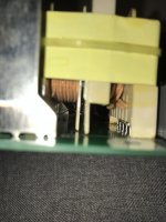
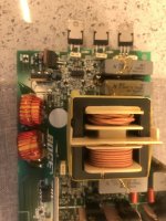
I agree that it is rather obsolete this kind of mechanism. By the pics of the trafo, it seems to be resonant or quasiresonant PWM circuit, a relatively new approach to SMPS, but the rectifier using doubler for 110VCA is very a old solution.
I agree that it is rather obsolete this kind of mechanism. By the pics of the trafo, it seems to be resonant or quasiresonant PWM circuit, a relatively new approach to SMPS, but the rectifier using doubler for 110VCA is very a old solution.
If needed, I would swap the capacitors for higher voltage types.
And the simplest solution would be a step down transformer, and the next may be a modified laptop SMPS, though I suspect that apart from the 5 and 12 V supplies, a third for the audio amp section is involved.
And the simplest solution would be a step down transformer, and the next may be a modified laptop SMPS, though I suspect that apart from the 5 and 12 V supplies, a third for the audio amp section is involved.
Know am confused 😂, so if I change the cap to 400v what uf as I can’t find any high as 470uf with 400v any links? Thank you all for your time and reply’s 🙏🏼
Guys, may I urge caution?
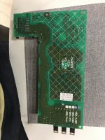
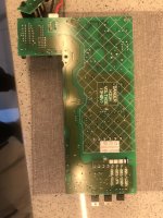
The PCB is clearly marked in the first post as being 120V only. Either it has been designed for 120V or it has been set up for 120V.

The PCB is a double sided design and instructions to cut tracks aimed at someone of unknown ability or knowledge are dangerous.
While it may be possible to adapt or modify for 230V operation, please be very clear with any instructions as I wouldn't like the OP to suffer injury.
I would suspect that the design is capable of being built to suit either voltage, this would make sense from a production perspective, especially as the board has tick boxes for both options.
I also suspect that JP1 is a prime candidate for setting the voltage. A jumper is there for a reason.

Now if one of our experts can chime in with easy to follow instructions on how to verify and modify in a safe manner then I will sleep better tonight.
The PCB is clearly marked in the first post as being 120V only. Either it has been designed for 120V or it has been set up for 120V.
The PCB is a double sided design and instructions to cut tracks aimed at someone of unknown ability or knowledge are dangerous.
While it may be possible to adapt or modify for 230V operation, please be very clear with any instructions as I wouldn't like the OP to suffer injury.
I would suspect that the design is capable of being built to suit either voltage, this would make sense from a production perspective, especially as the board has tick boxes for both options.
I also suspect that JP1 is a prime candidate for setting the voltage. A jumper is there for a reason.
Now if one of our experts can chime in with easy to follow instructions on how to verify and modify in a safe manner then I will sleep better tonight.
Thank you for your reply and for everyone else’s reply, Ave mange to order a second hand sub that is 230v Uk so will take pcb out and try and compare I will post photos of that pcb too, my knowledge is far as Soldiering and a bit about the caps and resistor I know, I also know how to discharge the caps, I have studied electronics in college and am a registered Electrician, the bit about jp1 is something am looking atGuys, may I urge caution?
The PCB is clearly marked in the first post as being 120V only. Either it has been designed for 120V or it has been set up for 120V. View attachment 1123536
The PCB is a double sided design and instructions to cut tracks aimed at someone of unknown ability or knowledge are dangerous.
While it may be possible to adapt or modify for 230V operation, please be very clear with any instructions as I wouldn't like the OP to suffer injury.
I would suspect that the design is capable of being built to suit either voltage, this would make sense from a production perspective, especially as the board has tick boxes for both options.
I also suspect that JP1 is a prime candidate for setting the voltage. A jumper is there for a reason.
View attachment 1123537
Now if one of our experts can chime in with easy to follow instructions on how to verify and modify in a safe manner then I will sleep better tonight.
Try and find a service manual or a schematic.
Japan is 100V AC mains, I think.
If the PCB is marked for different regions, it must be a production level decision.
After you get the manual, or a schematic, it will be much more clear on how (and whether) to proceed.
Or you could build a new supply, possibly external.
Japan is 100V AC mains, I think.
If the PCB is marked for different regions, it must be a production level decision.
After you get the manual, or a schematic, it will be much more clear on how (and whether) to proceed.
Or you could build a new supply, possibly external.
You've no chance of getting a Bose schematic.
If you can trace the jumper & if it matches position 'S' in the attached schematic then you're good to go.
If you can't see the tracks then check for continuity.

If you can trace the jumper & if it matches position 'S' in the attached schematic then you're good to go.
If you can't see the tracks then check for continuity.
I would prefer to reverse engineer the power supply circuit including all line voltage options before any replacing components or cutting jumpers, tracks and wires, just to prevent an unwanted second big bang from happening. If handyj feels uncomfortable in doing this, posting sharp photo's of both sides of the pcb might be helpfull.Guys, may I urge caution?
...
Now if one of our experts can chime in with easy to follow instructions on how to verify and modify in a safe manner then I will sleep better tonight.
The top photos of both side are sharp if you click on images it you can zoom in, I’ll add more photos tomorrowI would prefer to reverse engineer the power supply circuit including all line voltage options before any replacing components or cutting jumpers, tracks and wires, just to prevent an unwanted second big bang from happening. If handyj feels uncomfortable in doing this, posting sharp photo's of both sides of the pcb might be helpfull.
The whole section, you seem to have posted only a part of the supply.
It is normally a bridge rectifier, smoothing capacitors, then high frequency switching, ferrite transformers, secondary rectifiers and smoothing capacitors, and a feedback loop so the SMPS controller can change the voltage as needed.
Please zoom out, and take photos in a way that top and bottom edges are oriented the same way in both photos.
Feel free to add arrows and so on.
The whole section, you seem to have posted only a part of the supply.
It is normally a bridge rectifier, smoothing capacitors, then high frequency switching, ferrite transformers, secondary rectifiers and smoothing capacitors, and a feedback loop so the SMPS controller can change the voltage as needed.
Please zoom out, and take photos in a way that top and bottom edges are oriented the same way in both photos.
Feel free to add arrows and so on.
It only has extra one bit and then the board gown the Outher boards that are low power, if you need more photo please let me know, thank youThe whole section, you seem to have posted only a part of the supply.
It is normally a bridge rectifier, smoothing capacitors, then high frequency switching, ferrite transformers, secondary rectifiers and smoothing capacitors, and a feedback loop so the SMPS controller can change the voltage as needed.
Please zoom out, and take photos in a way that top and bottom edges are oriented the same way in both photos.
Feel free to add arrows and so on.
Attachments
-
 C5B73AC0-4220-4F55-8C4C-A8ED7BB44D79.jpeg299 KB · Views: 74
 -
 32138ECE-AABF-4BE6-A0CE-3F611DA5F0AA.jpeg532.1 KB · Views: 72
 -
 EE45FF42-3436-4C16-AB89-0C672C5CF5DB.jpeg337.3 KB · Views: 88
 -
 AC42F053-DD2A-424E-A84E-AB57FFFF7821.jpeg407.5 KB · Views: 80
 -
 D75DC7FF-09ED-4C43-98AD-8AA68E096FDB.jpeg586.7 KB · Views: 74
 -
 B50242C0-A378-4F06-A9CB-E6BB610033C8.jpeg439.6 KB · Views: 80
 -
 AA9E9F27-A9D1-4C3F-8988-DBEF6766EC2F.jpeg471.9 KB · Views: 77
 -
 BCED671D-D8C5-4DAF-9F3B-2F79660E689D.jpeg716.6 KB · Views: 74
My first conclusion is that this ps board is made for the US market exclusively, leaving out all unneccessary other components.
There are many open spaces for unknown parts visible on AA9E9F27-A9D1-4C3F-8988-DBEF6766EC2F.jpeg (7th photo).
Because these parts are unknown (estimated at best), I would prefer a 240:110 transformer here to avoid many and various problems and unsafe operation.
There are many open spaces for unknown parts visible on AA9E9F27-A9D1-4C3F-8988-DBEF6766EC2F.jpeg (7th photo).
Because these parts are unknown (estimated at best), I would prefer a 240:110 transformer here to avoid many and various problems and unsafe operation.
- Home
- Amplifiers
- Power Supplies
- Change power supply from 110v to 230v bose pa 18/48