I’ve been slowly working on building a 5 channel audio amplifier to replace my denon AVR amplifier. I actually went to school for electrical and computer engineering, but sadly, we never really did any real world electrical engineering. So this project for me is sort of my own personal university course where I’m trying to learn and acquire all the skills I probably should have had.
I’ve been making all the PCBs myself for the digital logic, and will ultimately try to decode the Dolby digital from spdif and use that to run the channels. In the meantime though I just completed the first audio channel and did a test today
All I can say is wow. I had high expectations, but it’s like having a brand new set of speakers and stereo. I have a set of Dali Oberón 3 speakers which were recommended to me, and I always thought they lacked a bit of everything. But they absolutely sound amazing now. And when I say they, I only have one channel so far, so I can’t to hear what real stereo sounds like.
At loud listening volume, the amp went from 6 watts total (including the digital circuits) to 9 watts, so only 3 watts of power. And to think I was worried that 300 VA wouldn’t be enough. I don’t think I can get much louder without offending my neighbours.
The only things so far that are potential issues are:
1) I am just using an RCA Jack for the input for now, and I ran the RCA ground to the input of the LM3886 and used it as my signal ground. This sounded horrible. It wasn’t until I also grounded this to the main ground that it sounded normal. I would have thought my laptop, which was the audio source over the headphone jack, would have acted as the ground, no? Anyways, now that it’s grounded, it seems fine.
2) while sitting on the couch with no audio playing, I don’t hear a thing. But if I put my ear up against the speaker I hear a very faint noise. It sounds sort of square wave ish so I’m thinking it’s rectifier noise. Is it a reasonable expectation that this sound should disappear completely if it’s grounded properly, or is it normal to hear a faint background noise close up?
3) every 30 minutes or so I hear a single quick audio tick. It almost sounds like a digital artifact. The only place I can think it might be coming from is a small beer fridge that’s on the same circuit. I haven’t tested this yet, but I wonder if when it kicks in that it causes that tick on the audio. If that’s the case, anything I could do to suppress it?
Thanks everyone. This has been a rewarding project so far, and I can’t wait to keep working on it and getting the rest together. Also a shout out to Tom and his website as I referenced it lots during this build (but perhaps not enough when it comes to grounding!) cheers.
Attachments


You'll probably find this informative: https://neurochrome.com/pages/taming-the-lm3886-chip-amplifier
The tick every 30 minutes or so could be EMI/RFI related. I'd add a filter on the input of the amp. I'll often use an LC filter, but an RC one with a cutoff around 100-200 kHz will work also.
If you ground the input to the amp the output should be quiet. On very efficient speakers you might hear a faint hiss with your ear against the speaker cone, but that's about it. You should not have any hum or buzz.
Tom
Sorry, you mean on each audio input to each channel? Isn’t there already a low pass filter baked into the LM3886 (I used your design I think from your website).You'll probably find this informative: https://neurochrome.com/pages/taming-the-lm3886-chip-amplifier
The tick every 30 minutes or so could be EMI/RFI related. I'd add a filter on the input of the amp. I'll often use an LC filter, but an RC one with a cutoff around 100-200 kHz will work also.
If you ground the input to the amp the output should be quiet. On very efficient speakers you might hear a faint hiss with your ear against the speaker cone, but that's about it. You should not have any hum or buzz.
Tom
Could you please share how are you going to decode Dolby Digital? Any articles or books recomendations?and will ultimately try to decode the Dolby digital from spdif and use that to run the channels
Thanks!
I’ll open source it all when (if) I get it working. I have two plans of attack. The first is to use the CS8416 to decode the SPDIF and then a STA310 chip to decode the Dolby digital. Then run that into a PCM1602 DAC. If that doesn’t work, I’m going to just do the decoding myself in software using a STM32F107 chip (which was four I2S lines, one for input, and three for output). I’m hoping the first one works as I don’t really feel like tackling the second yet.Could you please share how are you going to decode Dolby Digital? Any articles or books recomendations?
Thanks!
The STA310 is a "Dolby-certified" decoder that will decode not only AC3 but also DTS & MPEG Multichannel. I can say this with confidence as I just finished making a processing unit using this chip very very recently (details here). Also, the STA310 has its own internal S/PDIF decoder and does not need a chip like CS8416 outside of it.
A few tips on the STA310:
All the best.
A few tips on the STA310:
- Tie all unused pins to VDD/GND appropriately. Do not float.
- It draws about 500mA from the 3.3V supply during AC3/DTS decoding, so just make sure that you meet this requirement properly.
- Add an extra filter to the 2.5V supply that feeds the internal S/PDIF / PLL. Use a solid ground plane and run both the S/PDIF connections all the way to the decoder as you'd do for truly differential signals.
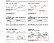
- The datasheet does not mention any DTS status registers like it does for AC3/MPEG. However, I've attached these details below. See the DTS specification to make sense of the terms AMODE, RATE, SFREQ etc.
All the best.
Attachments
Thanks for much for your response! I haven't met a single person that has used this chip, so it's definitely helpful to have someone to discuss it with.The STA310 is a "Dolby-certified" decoder that will decode not only AC3 but also DTS & MPEG Multichannel. I can say this with confidence as I just finished making a processing unit using this chip very very recently (details here). Also, the STA310 has its own internal S/PDIF decoder and does not need a chip like CS8416 outside of it.
A few tips on the STA310:
- Tie all unused pins to VDD/GND appropriately. Do not float.
- It draws about 500mA from the 3.3V supply during AC3/DTS decoding, so just make sure that you meet this requirement properly.
- Add an extra filter to the 2.5V supply that feeds the internal S/PDIF / PLL. Use a solid ground plane and run both the S/PDIF connections all the way to the decoder as you'd do for truly differential signals.
- The datasheet does not mention any DTS status registers like it does for AC3/MPEG. However, I've attached these details below. See the DTS specification to make sense of the terms AMODE, RATE, SFREQ etc.
All the best.
Any chance you can share a basic schematic that you did for yours? I have one ready, and one PCB assembled, but I don't want to waste my time if it's wrong (since each chip is about $10 I think). I'm literally just trying to get SPDIF into 3 I2S channels.
Some of the questions I have are:
1) I'm using the I2C interface, so I left the parallel interface pins floating.. is that wrong? Did you tie them all to zero?
2) Did you use any type of resistor for the SPDIF connection? I think I have 75 ohm on the CS8416 for impedence matching.
Well, it seems people have successfully used it before, for example, the following thread has a working circuit diagram and pseudo-code within it, if you look properly. However, it is worth noting that the chip (though very capable) has not been properly documented, which makes it very discouraging to try.Thanks for much for your response! I haven't met a single person that has used this chip, so it's definitely helpful to have someone to discuss it with.
https://www.diyaudio.com/community/...gether-to-control-a-sta310-ac3-decoder.38978/
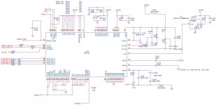
Firstly, make sure you're able to get this chip, as it is already obsolete and therefore no longer manufactured. My schematic is largely the same as what's within the ST documentation (attached).Any chance you can share a basic schematic that you did for yours? I have one ready, and one PCB assembled, but I don't want to waste my time if it's wrong (since each chip is about $10 I think). I'm literally just trying to get SPDIF into 3 I2S channels.
I did +VDD, zero should be fine as well but any active low inputs need to be tied to VDD, as opposed to GND.1) I'm using the I2C interface, so I left the parallel interface pins floating.. is that wrong? Did you tie them all to zero?
This is not about whether you're using the parallel interface, but to ensure that there is no excessive current drawn by the chip due to any floating inputs (customary CMOS "manners"). If you've any doubts, see the ST documentation that correctly terminates each input to a known potential.
Yes, S/PDIF cables are supposed to be terminated at characteristic impedance, which is usually 75 ohms (110 ohms for AES/EBU). Also, I used the S/PDIF receiver within the STA310, and not a separate chip like CS8416.2) Did you use any type of resistor for the SPDIF connection? I think I have 75 ohm on the CS8416 for impedence matching.
And one more thing, just do not use an SMD regulator for the 3.3V supply. Use TO-220/D2PAK with appropriate heatsinking. I used a cheap brand called AMS1117-3.3 that gave out >3.6V spikes during heating, also causing the S/PDIF PLL to unlock and drop the signal. However, the 2.5V regulator may very well be SMD, as the current draw from this supply is very small.
Attachments
Thank you. That all helps a lot. I don’t see the 75R resistor in that schematic I don’t think.
And yes, I already have several of these chips. There is some tv repair place in Europe that seems to have a stock I’ve bought a few from.
And yes, I already have several of these chips. There is some tv repair place in Europe that seems to have a stock I’ve bought a few from.
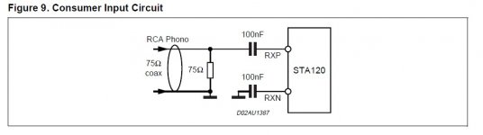
My 75R resistor is part of the S/PDIF multiplexer front end, and not near the decoder chip. Refer to STA120 datasheet for the recommended S/PDIF connection. Also, do you have the STM documentation for this chip ? It clearly shows the 75R termination.
My 75R resistor is part of the S/PDIF multiplexer front end, and not near the decoder chip. Refer to STA120 datasheet for the recommended S/PDIF connection. Also, do you have the STM documentation for this chip ? It clearly shows the 75R termination.
I have the "6+2-Ch. multistandard audio decoder" document, and the "STA310 Getting Started" guide. That's all I have so far.
Here you go. Also note that you must use the S/PDIF receiver for auto-detection, and the I2S input doesn't have this feature.
Attachments
Last edited:
Here you go.
Thank you! I have my amp working with RCA inputs so far, and it's great. But I'd really like to ditch my Denon amplifier and switch to this. But until I'm done this circuit, I can't.. Appreciate it.. I'll massage my PCB a bit more and make an attempt in a few weeks. I'll let you know how it goes!
Here you go. Also note that you must use the S/PDIF receiver for auto-detection, and the I2S input doesn't have this feature.
What did you end up using for your DAC after the STA310? I'm planning on using the PCM1602A 6 channel DAC, but just curious if you have any recommendations on that? Thanks again.
I used PCM1680, but recommend 1690 (differential out) if you can afford it. I had PCM1602 samples with me but chose 1680, as it was I2C.
Ok cool. What was your general philosophy for the post DAC lpf? Is a 12db/octave 2nd order butter worth enough? Where did you put your corner frequency, around 22kHz? It looks like it’s mostly for the out of band noise starting around 1.5x fs so doesn’t seem to need to be too sharp
No need for anything sharp, 2nd order, with approximately 25-30kHz cutoff will do just alright.
Awesome, thanks. I've been stumbling through all these new areas, appreciate having someone to bounce these things off of. I'm about a week from trying to get the decoder working, stay tuned 🙂
Any photos with your progress? 🙂Awesome, thanks. I've been stumbling through all these new areas, appreciate having someone to bounce these things off of. I'm about a week from trying to get the decoder working, stay tuned 🙂
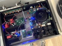
Sure. I'm mostly in a holding pattern right now until the new PCBs arrive this week from JLCPCB.
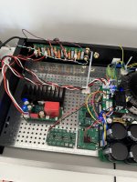
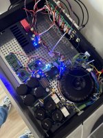
But here's the current progress. I had a slight grounding issue on the original LM3886 power amplifiers, so I have to move these to the new boards. But I should have that done on the weekend. But it still sounds great right now, and I have three channels build and working in the amp.
So what's next is:
1) Finish the 5 amplifiers later this week, and test them independently with the current RCA cables
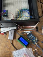
2) I built a custom STM32 board on the weekend that's good enough to use I2C for to configure the STA310 and my DAC, so I should be able to start that once the new boards arrive. I have the LCD working, and am going to start working on the user interface and what not via the LCD
3) I have a second test chassis I wired up just to test the digital logic (so I don't have to hover over my working amplifier with my laptop and STM32 programmer)
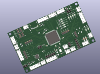
So I figure I'll have the analog stuff all done this weekend, at which point I can secure the heatsinks and all five LM3886s. Then I can switch to the digital logic. The boards I have to build are: 1) the new microprocessor board 2) the new DAC board 3) the new STA310 board 4) The post DAC filters (I've tested a board already though, so this will work). I also recently stumbled upon the PT2323 IC which looks interesting, so when this is all working, I may try to use that to connect four external stereo inputs to the 6 channel system.
I'm waiting for a new LCD to arrive, and then I'll send off the CNC file to Moduship.biz here in Europe to CNC the front panel - it'll have space for two knobs (volume and input selector), power button, power light, and the LCD display.
It's coming together nicely!
But here's the current progress. I had a slight grounding issue on the original LM3886 power amplifiers, so I have to move these to the new boards. But I should have that done on the weekend. But it still sounds great right now, and I have three channels build and working in the amp.
So what's next is:
1) Finish the 5 amplifiers later this week, and test them independently with the current RCA cables
2) I built a custom STM32 board on the weekend that's good enough to use I2C for to configure the STA310 and my DAC, so I should be able to start that once the new boards arrive. I have the LCD working, and am going to start working on the user interface and what not via the LCD
3) I have a second test chassis I wired up just to test the digital logic (so I don't have to hover over my working amplifier with my laptop and STM32 programmer)
So I figure I'll have the analog stuff all done this weekend, at which point I can secure the heatsinks and all five LM3886s. Then I can switch to the digital logic. The boards I have to build are: 1) the new microprocessor board 2) the new DAC board 3) the new STA310 board 4) The post DAC filters (I've tested a board already though, so this will work). I also recently stumbled upon the PT2323 IC which looks interesting, so when this is all working, I may try to use that to connect four external stereo inputs to the 6 channel system.
I'm waiting for a new LCD to arrive, and then I'll send off the CNC file to Moduship.biz here in Europe to CNC the front panel - it'll have space for two knobs (volume and input selector), power button, power light, and the LCD display.
It's coming together nicely!
Attachments
- Home
- Amplifiers
- Chip Amps
- LM3886 5.1 build