Hi,
that clears things up. Your Qt has nothing to do with the Qts value of the T/S parameter stated in most any drivers datasheet.
T&S treated the Bass driver and the Box as HP filters not as BPs.
Qts is a value closely related to a small bandwidth range around the free air resonance Fs.
It allows a quick calculation of target volume Vb, target resonance Fb, and target Q-factor Qtb of the Highpass called Box.
Your Qt is rather a definition of the useable frequency range of a driver.
It is not used for the calculation of cabinet dimensions in the classic Thiele-Small formulas.
Using it in a design thread for a subwoofer can be quite misleading.
jauu
Calvin
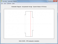
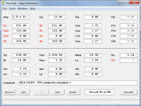
To calculate the PPD subwoofer in Hornresp, use the option "The speaker element in an H shaped Open baffle or a U shaped Open baffle".
As GM has pointed out in Post #9, the PPD subwoofer design can also be simulated in Hornresp using the BP6P model. The results will be a little different and possibly more accurate because internal end corrections are then taken into account on the two ports.
Attachments

If I understand it correctly, you need to use a fair amount of boost at the low end as with any dipole, am I correct?
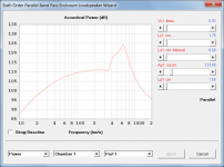
I also see that you are displaying the output of the front port only - should one not get a massive cancellation between the front and back, getting something like this instead?

I also see that you are displaying the output of the front port only - should one not get a massive cancellation between the front and back, getting something like this instead?
Last edited:
If I understand it correctly, you need to use a fair amount of boost at the low end as with any dipole, am I correct?
The combined output will be significantly reduced at low frequencies due to the two outputs being out of phase. If the total system is being considered then yes, considerable bass enhancement will be required to achieve an acceptable extended low frequency response.
I also see that you are displaying the output of the front port only - should one not get a massive cancellation between the front and back, getting something like this instead?
The output of the front port only was given to allow a direct comparison with the grey response trace shown in Post #38.
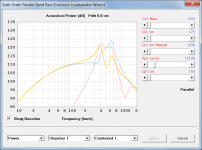
Any dipole-type system is going to be significantly compromised at bass frequencies unless one of the outputs is effectively "isolated" from the listener in some way. A practical loudspeaker would need to be positioned and oriented such that the output from the rear is not a significant contributor to the overall response observed by the listener.
As shown in your chart, and as expected given the system topology and dimensions, the overall combined response characteristics are quite similar to those of a relatively narrow-band bandpass filter.
For Ripol and PPD, this recommendation does not work. On the contrary, the subwoofer should be located in the room in such a way as to maximize the use of both ports. That is, in practice, this means that there should be at least 1-1.5 meters from the any port to the nearest wall.Any dipole-type system is going to be significantly compromised at bass frequencies unless one of the outputs is effectively "isolated" from the listener in some way. A practical loudspeaker would need to be positioned and oriented such that the output from the rear is not a significant contributor to the overall response observed by the listener.
For Ripol and PPD, this recommendation does not work. On the contrary, the subwoofer should be located in the room in such a way as to maximize the use of both ports. That is, in practice, this means that there should be at least 1-1.5 meters from the any port to the nearest wall.
Very interesting.
Do you have an explanation for the results you are seeing?
Are room resonances enhancing the low frequency response, perhaps?
What happens if measurements are done outside?
I have no practical experience with such speakers and relied on generally-accepted acoustic dipole theory when framing my answers to Post #43. It is interesting though, that two completely different Hornresp simulation models, neither of which really know that they are looking at a dipole system, come up with essentially similar results, and that the characteristics of those results appear to be consistent with classical dipole theory.
Attachments

measurements from 20 cm from the port.
What does the combined response look like, measured at least a metre away from the system, and in open air?
I do not have a mathematical model and explanation of the work of the PPD. There are only my own thoughts and assumptions from the Tornadoacoustics forum how it works: There are two objective "counter factors" in the PPD. The first - the aperture of radiation into the air (into the room) is reduced, therefore, the already low impedance of the load of the acc. system by the medium is reduced. The second - an acoustic transformer is working, decreasing in pressure, but increasing in speed, which leads to an increase in the impedance of the load of the diffuser by the chambers, increases in Ktr. ^ 2, and Ktr. equal in speed to the Sd/Sport ratio, i.e. when the hole is narrowed, an increase occurs, which increases the radiation efficiency and acoustically damps the natural oscillations of the movement not against the acoustic resistance panel (decreased efficiency), but "about the air" (as it should be). Here's an interesting twist. Actually.Do you have an explanation for the results you are seeing?
Are room resonances enhancing the low frequency response, perhaps?
What happens if measurements are done outside?
I don't think the room resonances are helping to pump up the low frequencies in this acoustic design. Rather, on the contrary, they are minimized relative to the bass-reflex design.
On the street, all measurements remain valid and look even better than indoors.
This is a very interesting debate. My open backed 2x12 SLOB(https://www.diyaudio.com/community/threads/slob-2x12-subwoofer-for-near-field.384529/), which is quite similar to PPD (except for the different areas of the slots) measures like this (50 cm away) in a room. https://www.diyaudio.com/community/attachments/slob2x12-50cm-jpg.1046419/
I need to repeat the in-room measurements further away (I did not store them), now it is placed only a few cm from the wall and IIRC, I could not see any bass reduction (or very little). I cannot explain this, maybe it is due to the placement, but the bass seems to be quite consistent around the room and I even did not see the expected reduction in bass in other rooms (maybe too leaky door?). I need to try again with just the sub on.
I need to repeat the in-room measurements further away (I did not store them), now it is placed only a few cm from the wall and IIRC, I could not see any bass reduction (or very little). I cannot explain this, maybe it is due to the placement, but the bass seems to be quite consistent around the room and I even did not see the expected reduction in bass in other rooms (maybe too leaky door?). I need to try again with just the sub on.
If your sub also has open ports on the back side, then your sub design is essentially a repol. And so you can see the uneven frequency response in the region of 200 Hz. This is because the port chambers has a fairly large volumes, and their shapes and locations relative to the speakers is a shortened waveguides.I need to repeat the in-room measurements further away (I did not store them), now it is placed only a few cm from the wall and IIRC, I could not see any bass reduction (or very little). I cannot explain this, maybe it is due to the placement, but the bass seems to be quite consistent around the room and I even did not see the expected reduction in bass in other rooms (maybe too leaky door?). I need to try again with just the sub on.
To see / hear the difference in sound pressure when the subwoofer is located near the wall and at a distance from it, measurements / listening should be carried out not near the port, but at the listening point, at a distance of several meters, where the total pressure from both ports already begins to act.
On the street, all measurements remain valid and look even better than indoors.
For the PPD subwoofer system to perform as indicated, the two outputs would need to have very different levels to avoid significant destructive interference at low frequencies.
The system itself is relatively easy to model and simulations should be reasonably accurate. The results given below are consistent with those that one would expect to see from the system shown in the attachment. What I don't understand is how the actual output levels can be so different to the simulated ones.
Just to positively confirm that the actual levels are so very different to each other, would it be possible to accurately measure the outputs from each port separately, with the microphone close to the port being measured, and with the whole PPD loudspeaker system well clear of any reflecting surfaces?
Simulation:
Front side results at 100 Hz:
Front port area = 133 cm^2
Diaphragm front side Ra = 0.0023 ohms
Diaphragm front side Xa = 0.0418 ohms
Magnitude of acoustical impedance loading front side of diaphragm = 0.0419 ohms
Peak pressure on front side of diaphragm = 317.2933 Pa
Front port output air particle velocity = 5.8088 m/s
Front port output SPL = 110.3374 dB
Front port output phase = 43.2463 deg
Rear side results at 100 Hz:
Rear port area = 266 cm^2
Diaphragm rear side Ra = 0.0024 ohms
Diaphragm rear side Xa = 0.0342 ohms
Magnitude of acoustical impedance loading rear side of diaphragm = 0.0343 ohms
Peak pressure on rear side of diaphragm = 259.6571 Pa
Rear port output air particle velocity = 2.9649 m/s
Rear port output SPL = 110.5062 dB
Rear port output phase = -136.8685 deg (almost exactly 180 degrees different to front port)
Attachments
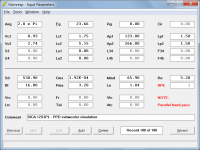
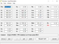
please show a screenshot of the hornresp main window with your parameters? Here is mine for H frame option simulationSimulation:
Attachments
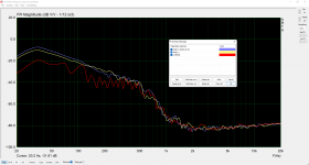
These are measurements of the PPD built on the GW212-4 speakerJust to positively confirm that the actual levels are so very different to each other, would it be possible to accurately measure the outputs from each port separately, with the microphone close to the port being measured, and with the whole PPD loudspeaker system well clear of any reflecting surfaces?
Attachments
please show a screenshot of the hornresp main window with your parameters?
Screenprint attached.
(The design was modelled as shown simply so that the impedance, pressure and velocity results given in Post #51 could be readily found).
Attachments
These are measurements of the PPD built on the GW212-4 speaker
Thanks. The front and rear outputs appear to be almost the same, which is what I would expect to see. What I still don't understand though, is why when the two signals are combined they don't effectively cancel each other out at low frequencies due to the 180 degree phase difference. It is a real mystery to me!
Is it not because push-pull dipole nulls out the side radiation like a bass firewall? So there's little sidewall/ceiling/floor reflection, and the rear reflection off the wall is phase-delayed by ~2m becoming constructive ~28-140hz (any wavelength 1.2-6X the path length). I'm really a novice at OB and PP but my tests and listening experience fit the simple math.Thanks. The front and rear outputs appear to be almost the same, which is what I would expect to see. What I still don't understand though, is why when the two signals are combined they don't effectively cancel each other out at low frequencies due to the 180 degree phase difference. It is a real mystery to me!
(I use the same vector-sum math for TL.)
Last edited:
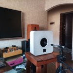
With the microphones as close as the photo suggests you would not see any cancellation. With this design I would expect to see a dipole response in the room like a ripole design or the original OB subs that Celestion used with their SL600 design.Differing vent phase due to differing compression ratio?
This is true, except that the distortion is noticeably less, this can be seen not only in the measurements, but is immediately felt by ear. I think this is due to the small volumes of the chambers and the direct-flow design, which greatly facilitates the operation of the bass driver.With the microphones as close as the photo suggests you would not see any cancellation. With this design I would expect to see a dipole response in the room like a ripole design or the original OB subs that Celestion used with their SL600 design.
- Home
- Loudspeakers
- Subwoofers
- PPD subwoofer