Is there any plans?What drivers will work in the design I have currently Beyma 12BR70 4 drivers. Can you share the dimentions so I can try
Wow your right the closes I can find are .16 and .17 and and that's all 4 15in and one 10in that go down to 30 and 40 Hz but they are very expensiveTo play 25-500 Hz requires a 2x25/500 = 0.1 Qts that historically only a powerful field coil driver could get this low, though I imagine a Neo motor could be built at a significant development cost.
Hi,
I find the idea of the PPD very interesting, but I'd liked to see any sensible measurements that support Your high claims.
Reducing a cabinet´s dimensions -and that is basically what is done here- seriously alters the output to the worse.
With the Ripole the dimensions of the chambers are extremely small already, but still large enough to add considerable virtual membrane weight.
This leads to the known sinking of the drivers base resonance Fb by up to 15Hz.
Reducing the dimensions further didn´t change much regarding the Fb, but only led to a drop in efficiency/output.
In other words ... make it as small, but no smaller.
Typically the Qts of suitable drivers ranged between a medium of 0.4-0.8 (+-0.1) rising from large sized drivers to smaller drivers.
A Qts as low as 0.1 would certainly be far off of the optimal for any kind of dipole so far ... it required huge amounts of LF-equalization ... so, what should make it suit the PPD?
So far I heard a lot of word of mouth but haven´t seen a correct simulation nor a single trustworthy figure of merit nor a sensible measurement that supports the high claims of the tiny PPD.
I really wished the superiority claims were true, since the idea behind is appealing, it´s dimensions are tiny, and it should be easier to build ... all good pros ... but so far I´m honestly not convinced at single bit that it improves matters over other dipoles and certain claims even contradict theory.
So please, put some flesh to the bones. 😉
jauu
Calvin
@GM: Where do You get the figure of 0.1 forQTs from? We´re not talking bandpass here.
@Alvipet: Are You by any chance related to Tornadacoustics?
Could it be we met in 2008 at the first DIY fair in Wetzlar in Germany?
Last edited:

So if I have 1 or 2 nos PPD beyma 12" subwoofer I can think of making acompact boombox I have Peerless TC9 3.5" FR driver what say friends a 2.1 system
It will be portable compact compared toa sealed or ported box.
It will be portable compact compared toa sealed or ported box.
Okay, let's try to sort out the evidence. Do you trust the simulation results in Hornresp?Hi,
I find the idea of the PPD very interesting, but I'd liked to see any sensible measurements that support Your high claims.
...
So please, put some flesh to the bones. 😉
@Alvipet: Are You by any chance related to Tornadacoustics?
Could it be we met in 2008 at the first DIY fair in Wetzlar in Germany?
Yes, I am one of the founders of Tornadacoustics website.
I did not visit Germany in 2008.
Why not? I think it makes sense to try.So if I have 1 or 2 nos PPD beyma 12" subwoofer I can think of making acompact boombox I have Peerless TC9 3.5" FR driver what say friends a 2.1 system
It will be portable compact compared toa sealed or ported box.
Hello @Alvipet
Does this driver seem suitable?
Sica 12 S 3 PL, 12 Zoll PA Driver
https://sica.it/wp-content/uploads/2021/02/Z007946.pdf
Nice, low loss construction; relatively strong motor/BL; relatively low mms; only FS seems to be a little on the high side.


Does this driver seem suitable?
Sica 12 S 3 PL, 12 Zoll PA Driver
https://sica.it/wp-content/uploads/2021/02/Z007946.pdf
Nice, low loss construction; relatively strong motor/BL; relatively low mms; only FS seems to be a little on the high side.
Last edited:
Yes, it is. Up to at least about 70 watts, you should not have problems with overloading and the coil going beyond the linear travel limit. The subwoofer amplifier must have good load control.Does this driver seem suitable?
I think I will use two of them per channel placed next to the main speaker (so four at all) and drive them with two Hypex plate amps.
This should be enough to have some fun 🙂
Thank you for your help!
This should be enough to have some fun 🙂
Thank you for your help!
You are welcome! I wish you a successful project!Thank you for your help!
Hi everyoneExample: Sd = 540 cm2, D magnet = 13.4 cm, S magnet = 140 cm2, S = 0,5 * 540 + 140 = 410 cm2, D holes = 22.8 cm
The hole in the front is 128 mm. The hole at the back is 224 mm. The size of my subwoofers is 386x386x140
This is a very interesting concept, and it seems that even a total novice like me could do it. Just to be sure:
Sd = Surface driver
D = diameter
S = surface
Or is that D for Depth
?
Could you share you simulations, is it in Hornresp or another package? I tried modelling the 12BR70 in Vitiux, without any success with the dimensions quoted and couldn’t get anything sensible. As I am wanting to know whether I can improve on an open baffle W frame arrangement for these http://www.loudspeakerdatabase.com/SEAS/XM004-04_L26RO4Y
SD = Surface (of the) diaphragmaSd = Surface driver
Yeah, normally for wide range apps is to design to the mean, so sqrt(25*500) = ~111.8, so 2*25/111.8 = a much more reasonable ~0.447 Qts' and use EQ to boost the response out to 500 Hz.Wow your right the closes I can find are .16 and .17 and and that's all 4 15in and one 10in that go down to 30 and 40 Hz but they are very expensive
@GM: Where do You get the figure of 0.1 forQTs from? We´re not talking bandpass here.
https://www.diyaudio.com/community/threads/ppd-subwoofer.393371/post-7206582
Well, it's acoustically a dipole BP6P since it has chambers on both sides and simple (baffle thickness) reflex vents, so guess we'll have to agree to disagree. 😉
Having written it out now Vs just visualizing it originally, it makes me wonder if the late, lamented DJK's analogy of the BWC being based on 'half square' antenna theory might be the best way to sim/apply it, i.e. a 3:1 ratio such that the 'vents' are a 1/4 WL apart and choose driver specs from this.
Greets!I find the idea of the PPD very interesting, but I'd liked to see any sensible measurements that support Your high claims.
Reducing a cabinet´s dimensions -and that is basically what is done here- seriously alters the output to the worse.
With the Ripole the dimensions of the chambers are extremely small already, but still large enough to add considerable virtual membrane weight.
Me too! As a 'hornie', I'm a big fan of (properly) designed BPs, but like you there's 'no replacement for displacement', so finding it hard to believe they can be small, powerful and efficient enough to keep thermal power distortion adequately low with such 'tight' fitting chambers, relatively small area vents.
For instance, when I've 'squeezed' a (mid) bass horn driver hard enough (sealed back) to reactance annul the horn it keeps the VC hot enough even at very low power to cause some thermal power distortion that audibly causes it to sound a bit 'relaxed' Vs in a typically sized sealed alignment where it sounds a bit 'faster' for lack of a better word.
Last edited:
Sd - is the effective area of the speaker diffuser.Hi everyone
This is a very interesting concept, and it seems that even a total novice like me could do it. Just to be sure:
Sd = Surface driver
D = diameter
S = surface
Or is that D for Depth
?
D - is the diameter of the magnet.
S magnet - The area of the magnet.
S = 1/2 * Sd + S magnet
D holes - is the diameter of the rear hole.
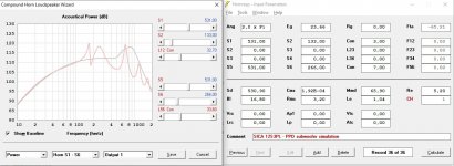
To calculate the PPD subwoofer in Hornresp, use the option "The speaker element in an H shaped Open baffle or a U shaped Open baffle".Could you share you simulations, is it in Hornresp or another package?
Just like in a traditional ripole, the cost of high bass quality is low efficiency. To compare PPD with ripole, I took for example the parameters of Sica 12 S 3 PL, which was asked about above. The gray graph is the front port for the PPD version, and the red graph is for the Axel ripole.Reducing a cabinet´s dimensions -and that is basically what is done here- seriously alters the output to the worse.
Attachments

Hi,
I don´t know about the qualities of hornresponse to sim a dipole, but certainly that simulation is not correct.
A almost identical response below 100Hz won´t even be plausible by simple intuition.
AkaBak was one of the few progs that gave results that correlated close with real measurements .... and the Hornresponse curves here differ grossly from that.
Unfortunately I´m not using AkaBak any more, but there are enough old threads with Sims around with Peerless SLS12 drivers et al.
So I´d rather rely on a proper measurement .... which would quickly tell the - probabely even not so small- differences between a PPD and other dipole styles.
@GM. Qts is used for the driver´s quality factor. The faktor You use is the Q of a bandpass. So we are talking different things here.
A driver with a Qts of only 0.1 would be very off of standard and it would dampen away any bass and as such be fully unsuitable for dipole subwoofer useage.
jauu
Calvin
If I follow, didn't imply/state otherwise; but to get T/S theory box loading from 25- 500 Hz requires a driver 0.1 Qt to 'push' the driver's upper mass corner to 500 Hz, though obviously since we're always 'robbing Peter to pay Paul' (trading efficiency for BW) we have to choose which we want most for whatever reason based on the needs of the app, hence my follow up response to put it in a more perspective, practical solution.
- Home
- Loudspeakers
- Subwoofers
- PPD subwoofer