I can agree with the first sentence, but this circuit does not "control" the current between the two output stages. The quiescent current (now called IQ in all the electronic ads - "Don't you want Low IQ?") will depend on the exact values of the gain setting resistors and such, which are essentially random. A servo circuit to set a specific, small voltage difference between the two outputs would do forced Class A, but I'm not sure if that's the best way to lower distortion. It would be interesting to measure distortion vs. that voltage difference.High output standing current is not necessary a bad thing. This current will keep the output stage in class A witch is required by some audiophile peoples.
I like the idea of bridged rather than parallel, for several reasons beyond needing to carefully match parallel outputs. Bridged pulls power from both + and - rails simultaneously, and the current from one rail always returns to the other. The parallel circuit pulls current from one rail at a time, and returns this current through the ground which can "pollute" the low-signal-level ground without careful ground path layout. Of course there are other considerations, you might need to drive a lower impedance speaker, or you may need the speaker connection to be ground-referenced (I'm not sure why this would be needed other than a user assuming it's always ground, maybe someone can tell me).
Then there's the idea of "Well I Just Need Moar Power" and as both the Neurochrome site and the app note says (with a schematic even), you can use a combination of bridged and parallel using four devices, or even three-on-each-side paralleled and bridged using six devices. All cautions apply about making sure paralleled outputs are indeed very close to being the same.
Then there's the idea of "Well I Just Need Moar Power" and as both the Neurochrome site and the app note says (with a schematic even), you can use a combination of bridged and parallel using four devices, or even three-on-each-side paralleled and bridged using six devices. All cautions apply about making sure paralleled outputs are indeed very close to being the same.
I'm sure the Neurochrome site is just fine, but there's this other document on bridging and paralleling those chips that you may want to read. I dare say it's as trustworthy as Neurochrome, because it's from the chip manufacturer:
https://www.ti.com/lit/an/snaa021b/snaa021b.pdf
No, it isn't, the paralleled application (fig 6, p13) in that document is a disaster. I feel sure Neurochrome does a lot better.
Except for the slew rate which doubles in the case of the bridge configuration, the rest of the parameters degrade. A speaker does not have a constant impedance. Even if it is declared to have 8Ω, its impedance can drop a lot at certain frequencies, even below 3Ω in some cases, which will generate very large distortions in the case of the bridge configuration that needs high impedance at the speakers. And the LM3886 having a maximum output current of only 7A is even less recommended for bridge configuration.

A pretty conservative worst-case estimate for momentary peak current is two to three times the DC current at max DC output voltage.
Say, you have +-28V rails which is good for about +-25V peak voltage, with a DCR of say, 5.6Ohms (for a "8Ohms" woofer) we get (2..3)*25/5.6 = 8.9..13.4A.
In a bridge config peak voltage and thus peak current doubles... there are good reasons why 3 LM3886 per bridge leg is the preferred choice for an amp that must handle nominal 4 Ohms speakers (and depending on the driver and usage it may still run into occasional over-current incidents, IME).
I wouldn't use the basic bridge using only two 3886's for anything else than 16Ohms drivers.
I liked the idea but after some simulations it became clear that there is no way to share the load evenly because:The best way to force two circuits to properly share a load is to have one master and one slave (apology to anyone offended by the terms but they are the industry standard) with their outputss tied together. Monitor the current in the master with a resistor in the output and force the current in the slave to be the same.
1. The output offset is cumulative and no good way to balance the two.
2. The slave will always see its own output as well as the master output, so the gain becomes imbalanced.
3. The input of LM3886 and similar has a very limited common mode range, so the slave has to have gain, driven from attenuated master output. Also, these chip amps have a minimum gain for stability.
I think the best plan is a pair of ~CFP power transistors driven from the supply rails, but there are issues and the available spice models for LM3886 are flawed so just how flawed is unknown. I think attempting to extend any chip is usually a bad idea. If you want a bigger amp, then go discrete. And we have a supply issue with LM3886 at the moment, a problem with any canned solution.
exactly
never got the whole master slave thing.
it basically guarantees more output offset on the slave
and the gain to be unmatched.
anyways
most people just use 1% resistors and parallel the things.
even if you added trimmers
no 2 chips are the same, and DC offset
is going to change with temperature.
the ballast resistors get hot?
no way.....
Use 0.1% resistors! The OP's schematic shows 0.1%, though they're missing the leading 0 and the decimal point is hard to see. All the schematics I see with paralleled chipamps show 0.1% resistors to set gain.most people just use 1% resistors and parallel the things.
Do you mean TDA7293?Why not try with STK series? There are amps up to 150W untill I remember.
I have started a thread here on those in parallel https://www.diyaudio.com/community/...7293-with-balanced-inputs.393272/post-7202304
May be, but there are some STK hybrid IC up to 150W. I used some of them for background music in supermarkets via 70V Transformers and they performed best than discrete options.
Not AT ALL, absolutely different case.
:
When paralleling power amplifiers, which is the case here, each one has its own "brain" (differential stage, main gain stage, most important: its own NFB net), hell bent on setting a definite output voltage.
Having 2 (or more) "brains" will result on them fighting each other to death to impose its own "solution"
The clumsy cludgy way to (sort of) "solve" that very real problem, self created I might add, is to:
1) make those "fighting brains" think alike .... which is not easy
I am looking into paralleling TDA7293 since they have a way to only use one “brain” to drive two or more ICs
Are you talking about R13 and R15?You can split a supply like this, but you need to use a divider across the two rails for the positive inputs instead of a single resistor to the (floating) ground. Or you can add a ground ~regulator that soaks up any bias current that might pull ground towards one of the rails.
No. Maybe the +/-15V uses the same supply ground as the +/-35V but that is not shown. If this actually works, then it must be. I'm talking about U1, not the power amps.Are you talking about R13 and R15?
Voltage offsets that I am getting are as follows:
Module one:
Before 0.1R resistors:
-1.5mV DC
1.4mV DC
At speaker output:
0.1mV DC
Module two (closer to psu):
Before 0.1R resistors:
-7.9mV DC
6.4mV DC
At speaker output:
-0.8mV DC
Module one:
Before 0.1R resistors:
-1.5mV DC
1.4mV DC
At speaker output:
0.1mV DC
Module two (closer to psu):
Before 0.1R resistors:
-7.9mV DC
6.4mV DC
At speaker output:
-0.8mV DC
So module 1 has about 15 mA cross conduction and module 2 has about 70 mA. Interesting that although module 2's offset is about 5X that of module 1 in both cases one output is positive and the other is negative. Neither module has 2 positives or 2 negatives. This could easily be a coincidence but it kind of seems like this is trying to tell you something.
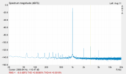
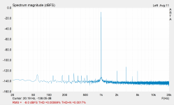
Here are attached measurements results for both channels.
Interestingly, the channel that is closer to the psu has offsets of -7.9mV and 6.4mV (-0.8mV) but shows less THD figures.
Interestingly, the channel that is closer to the psu has offsets of -7.9mV and 6.4mV (-0.8mV) but shows less THD figures.
Attachments
-
 channel1-smaller offset - mes2.PNG311.1 KB · Views: 71
 -
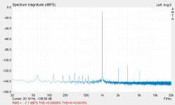 channel1-smaller offset.PNG428.8 KB · Views: 72
 -
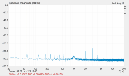 channel2 - bigger offset - closer to psu - vout 20v - cursor 60hz.PNG445.5 KB · Views: 79
 -
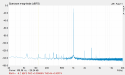 channel2 - bigger offset - closer to psu - vout 20v - cursor 120hz.PNG306.2 KB · Views: 67
 -
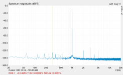 channel2 - bigger offset - closer to psu - vout 20v - cursor 300hz.PNG433.9 KB · Views: 76
 -
 channel2 - bigger offset - closer to psu - vout 20v - cursor 3000hz.PNG426.1 KB · Views: 70
 -
 channel2 - bigger offset - closer to psu - vout 20v.PNG370.5 KB · Views: 74
So module 1 has about 15 mA cross conduction and module 2 has about 70 mA. Interesting that although module 2's offset is about 5X that of module 1 in both cases one output is positive and the other is negative. Neither module has 2 positives or 2 negatives. This could easily be a coincidence but it kind of seems like this is trying to tell you something.
Here is how I measured:
Used Fluke 115
Negative probe is on the GND
Positive probe is tapping into different points on the PCB.
What do you mean by cross conduction?
- Home
- Amplifiers
- Chip Amps
- How bad input voltage offset difference between the two LM3886 will be in the schematics below?