Hi all.
Hope somebody can help.
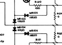
I have a Quad 303 which was faulty but i've fixed the fault ( open cct resistor on one of the driver boards ) and I intend to make 2 new amplifier boards and PSU board from scratch with HQ components throughout. Im puzzled by the schematic for the 303 and the actual board ? - The schematic shows 4 diodes around transistors tr103 and 104, but the actual amplifier has only 2 diodes ? I havent as yet verified why there are only 2 diodes fitted , but I will trace the tracks - any ideas what s going on with just the 2 diodes. Thanks . attached is a portion of the schematic im talking about
Attachments
Depending on the serial number of your amp you may be looking at the wrong schematic, as there were changes around that area of the circuit.
Hi all,
The serial # of the driver boards is 67986
it looks like its the version with the transistor , 2 diodes, and a preset for the bias. The boards serial # is M12038 rev 10
Ultimately, the problem i foresee is that after Ive re manufactured the driver amps, i wont be able to set the bias correctly ( i got rid of my dual beam oscilloscope ages ago ) ? - there is literature regarding the bias adjustment with simply a multimeter , Ill read up on that one.
Two of those diodes are bias, the other two are for the current limit/SOAR protectionDepending on the serial number of your amp you may be looking at the wrong schematic, as there were changes around that area of the circuit.
i would use the transistor version of the bias adjustment, and replace\do away with the 2 diodes version
So you are saying that Quad made a variant with the adjustable transistor Vbe multiplier instead of the two series diode arrangement seen on the widely shared Quad 303 schematic?i would use the transistor version of the bias adjustment, and replace\do away with the 2 diodes version
Yes. There are three extant 303 schematics, and the Vbe multiplier is on two of them, corresponding to the OP's unit which only has two diodes not four.
I was not aware of the number of updates to the 303 but found a link which shows some detail see http://www.meridian-audio.info/public/quad-303-service-data[1961].pdf
- Home
- Amplifiers
- Solid State
- QUAD 303 bias diode question / mystery ??
