These are 100V devices, so max +-50V for double rails (so +-60V is too much as the total would be up to 120V at full swing), and for single rail it would be max 100V, but in any case preferably a bit lower to be on the safe side, take also into account how much the mains voltage varies in your location.
Problem is that i have a consumer amplifier in front of me that has just one pair of 150/9150 rails of 60 V that claims 100W at 8R and 140W in 4 R
checked with the factory schematic all is correct , rails are supposed to be 60+60 volt
so math doesn't match
SOA calculation also doesn't match
Am I missing something ?
checked with the factory schematic all is correct , rails are supposed to be 60+60 volt
so math doesn't match
SOA calculation also doesn't match
Am I missing something ?
Well. Noting here match up. And do realy professional audio repairmen ask such beginner questions? It is +/-60Vdc. Not 60+60V. +/-60Vdc would result in about 150-170Wrms at 8ohm.
My guess. it is singel 60V rail, one rail pr ch. That will result in about 100W peak at 8ohm (at least in teory). But realy, that is a 50W at 8ohm amp ( again, in teory).
My guess. it is singel 60V rail, one rail pr ch. That will result in about 100W peak at 8ohm (at least in teory). But realy, that is a 50W at 8ohm amp ( again, in teory).
Last edited:

Short answer: +/-60V is way too much for them.
Straight from datasheet:
Will they work?
Maybe ... but not reliably.
Straight from datasheet:
ABSOLUTE MAXIMUM RATINGS (TC = 25 °C, unless otherwise noted)
PARAMETER SYMBOL LIMIT UNIT
Drain-Source Voltage VDS 100 V
Will they work?
Maybe ... but not reliably.
Problem is that i have a consumer amplifier in front of me that has just one pair of 150/9150 rails of 60 V that claims 100W at 8R and 140W in 4 R
checked with the factory schematic all is correct , rails are supposed to be 60+60 volt
so math doesn't match
SOA calculation also doesn't match
Am I missing something ?
What about rails sag under max. Load? I can bet that each rail sags more than 10 V at full load.
If manufacturer was so cheap with output transistors, it is to be expected the same with power supply.
Behind them there is a couple of huge trafos rated at least 300 W each Indeed in any non stabilised power supply rails will sag at some point but no where near the 10V you said at least in the usable area of the amplifier with 600W trafos behind 2 transistors per ch
So even worst the psu except high rails of +/-60V is also very beefy and that is killing the SOA any way you slice it
later on i will post pictures of the construction the brand and so on
yet again i had a long talk with the designer last night over the phone and discussion gets no better . they ve been doing that for 25 years and all is just fine
Please
if some is willing to do the math for me for comparison with my own calculations is more than welcome
Thank you very much
There is another fact that actual DS breakdown voltage is higher than specified max. safe operating Vds. Probably, manufacturer knows actual limit from experience.
Quick math confirms that SOA is not violated, but is challenged at max. power, even if rails don’t sag at all. At 140 W/4 Ohm, one MOSFET would have 107 W dissipation (60 V rail), and less than 80W with rail sag.
At 140 W/4 Ohm, load current is 5.92 A rms. Load voltage is 23.7 V rms.
(60 -23.7) * 5.92 = 214.9 W.
As one MOSFET is working only for a halfwave, dissipation is 107.5 W.
I stand by assessment that rails could sag 10 V. With light load of idle AB class amplifier, rails voltage will be close to secondary voltage x 1.41. From experience, high quality toroidal transformer at 1/3 rated power load and CRC supply will have output of secondary V x 1.25.
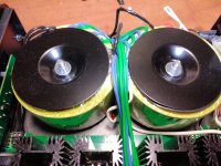
Amplifier under investigation is Atoll In 100 SE active model today and same proncipal applies for most previous models .
2 huge trafos 340 VA each connected in parallel
( error 1 : You cannot do that since you can never guarantee that trafos are exactly the same eventually one will load the other at some point )
So these trafos will produce +/- 60 V to supply the amplifier
(error 2 : you can not supply one 100 V transistor with rails +/-60 V at some point transistor will see 120V )
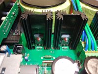
All tranistors are hooked on to far too smal heat sinks and individual heat sinks
( error 3: heat sink is too smal for the application any way you slice it ) and
( Error 4 individual heatsinks will never guarantee that transistors share the exact same temp resulting higher distortion and bad thermal stabilty )
There is no classic Vbe multiplier in the circuit except one thermistor that probably senses heat from the surrounding area near the heatsinks (?)
( error 5: without physical contact on the heat sinks thermal compenstation is always in "about " situation based on ambient temp and not real information )
( error 6: thermal compensation also is related to time if one transistor gets hot for any reason sensor will take catastrophic time to act )
Please comment

2 huge trafos 340 VA each connected in parallel
( error 1 : You cannot do that since you can never guarantee that trafos are exactly the same eventually one will load the other at some point )
So these trafos will produce +/- 60 V to supply the amplifier
(error 2 : you can not supply one 100 V transistor with rails +/-60 V at some point transistor will see 120V )
All tranistors are hooked on to far too smal heat sinks and individual heat sinks
( error 3: heat sink is too smal for the application any way you slice it ) and
( Error 4 individual heatsinks will never guarantee that transistors share the exact same temp resulting higher distortion and bad thermal stabilty )
There is no classic Vbe multiplier in the circuit except one thermistor that probably senses heat from the surrounding area near the heatsinks (?)
( error 5: without physical contact on the heat sinks thermal compenstation is always in "about " situation based on ambient temp and not real information )
( error 6: thermal compensation also is related to time if one transistor gets hot for any reason sensor will take catastrophic time to act )
Please comment
Attachments
These calculatins are made on the basis that load is 8R or 4 RThere is another fact that actual DS breakdown voltage is higher than specified max. safe operating Vds. Probably, manufacturer knows actual limit from experience.
Quick math confirms that SOA is not violated, but is challenged at max. power, even if rails don’t sag at all. At 140 W/4 Ohm, one MOSFET would have 107 W dissipation (60 V rail), and less than 80W with rail sag.
At 140 W/4 Ohm, load current is 5.92 A rms. Load voltage is 23.7 V rms.
(60 -23.7) * 5.92 = 214.9 W.
As one MOSFET is working only for a halfwave, dissipation is 107.5 W.
I stand by assessment that rails could sag 10 V. With light load of idle AB class amplifier, rails voltage will be close to secondary voltage x 1.41. From experience, high quality toroidal transformer at 1/3 rated power load and CRC supply will have output of secondary V x 1.25.
in reality the load is actually 6 ohms and it will dive to 4 ohms at some freq( may be less ) or 50 to some other
At 4 ohms in reality load is 3.3 and at some frequency it is possible to dive even close to 1.8 R
Math have to take this in mind also
Last edited:
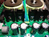
Notice also after the huge parallel trafos of 340VA each the tiny small rectifier ( only one ) no hetasink no nothing ....
that is a complete waste and bad use of parts
that is a complete waste and bad use of parts
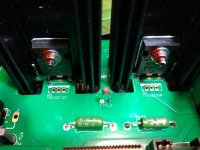
What do pics 3 to 5 show? Are these transistors on their humble heatsinks the output devices? Really?
Best regards!
Best regards!
yes these are the heatsinks for the output stageWhat do pics 3 to 5 show? Are these transistors on their humble heatsinks the output devices? Really?
Best regards!
simpleHow on earth is possible that such an incompetent company is still in business?
company is based in France probaly clients are people that do mild use of their product at home
Indeed if you look on the internet for problems in these amplifier you will find very little
so they survive clearly out of clear luck
none of these are reasons to overlook soa at that depth
its a poor design anyway you see it
Now I'm speechless 😱, especially regarding the fact that this is a rather huge chassis with ample space for sufficient heatsinks as the sidewalls and proper power devices mounted onto them.
Best regards!
Best regards!
- Home
- Amplifiers
- Solid State
- Rail Voltage for one pair IRFP150/9150