Appreciate everyone's input! Early next week when I get back in town I will take some pics, and measure everything requested. I do have some spare TL431s on hand in case they are bad. I am sure it'll get figured out before much longer. 🤞 🙂 What do you want pics of?
Hallo
Is it possible to drive out put stage B3 with preamplifier output impedance 500 ohm and 150 mA current?
thanks for answer
Is it possible to drive out put stage B3 with preamplifier output impedance 500 ohm and 150 mA current?
thanks for answer
Yes, but voltage swing defines whether you can drive it to full output or not.Hallo
Is it possible to drive out put stage B3 with preamplifier output impedance 500 ohm and 150 mA current?
thanks for answer
Plus, for that I’d use an F4 and not a BA-2 OS. Simpler to do.

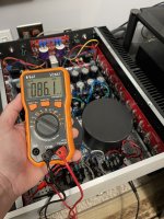
I just finished some testing as requested. What would you like to see pictures of? I did take some pics when I pulled the boards off the heatsinks two weeks ago of the boards front and back. The TL431 were very tricky for me to reach and measure, so these numbers are from just a second before my leads slipped off.
Results:
Left Channel:
V+ = 34.5
V- = -34.6
TL431 = ~2.4 but it varies by .1v or so
DC Offset = .2v
vDrop
Q1 to Q5 = .27 to .3 + and - (fluctuating at every mosfet)
Q6 = couldn't reach
Gate to Ground
Q1 to Q5 = either -4.0 or 4.5
Q6 = couldn't reach
Right Channel:
V+ = 37.5
V- = -34.7
TL431 = ~2.4 but it varies by .1v or so
DC Offset = 2.8v or so
vDrop
Q1 to Q6 = .25 to .29 + and - (fluctuating at every mosfet)
Gate to Ground
Q2 to Q6 = -2.7 or 6.1
Q1 = couldn't reach
Well I ended up buying a new set of matched transistors from the Store and one channel now works perfectly, completely silent with no music and clean and fun with music. The set also comes with a pair of TL431's so I replaced them too. My second channel has a remaining power supply issue that I am addressing on the Smooth Like Butter power supply thread. I'll post again once that issue is addressed and hopefully it'll also be good news 🙂
I'll keep the old transistors and maybe one day I'll learn how to test them.
I'll keep the old transistors and maybe one day I'll learn how to test them.
What’s the outlook running the input JFETs at 34.2v? Not that I plan on running the BA3 for hours a day every day but a few hours a week?
I replaced a bad transistor in the power supply, biased up all the channels to 80% for an hour till it was stable, played some music for a hour very happy, then the right channel went out. Crap. Opened it up and poked around and discovered my $10 Amazon special voltage regulator lost the positive leg. Sure, I can buy another one but now Im questioning that vs just running the JFETs at 34v. Or can I run them at a lower bias to compensate?
What are most people biasing the output stage at? NP says .25mA but says you can double that, however I’m at .4mA and I think the heatsinks are just too hot, so I’ll probably go down to .3 and see.
Toshiba or LS JFETs? I think you stand a 'better' chance with the Toshibas based on anecdotal information. I've seen varying accounts. Wiser minds should weigh in.
Nelson says this... "The supply voltage is only critical with respect to the voltage rating of the input JFETs, which are nominally 25 volts. In actual testing, they break down around 40 volts. I wouldn't worry about running them as high as 30V. Hot-rodding this circuit would likely involve cascoding the input Jfets to allow higher voltages."
I believe he was referring to Toshiba parts.
FWIW -
I varied the bias and P3 quite a bit across builds to see what I liked and to try and learn a bit. The calculated current through the source resistors for each output device is I think what you're looking for. If that's not what you're looking for, apologies. If that is what you're looking for, I think you'd like your current about 1000 times higher. 😉
I'm guessing you got your information from the BA-2 article... and just moved a decimal (added the m) perhaps?
"The amplifier prototype I built biased the output stage at 250 mA per output device, which measures as 250 mV across each of the 1 ohm Source resistors on the output stage. You will want to gently adjust P101 to this figure while watching the voltage across one of the 1 ohm resistors. When you reach that figure, use the multimeter to confirm a close value across all the 1 ohm output stage resistors. This figure will wander upwards as the output stage warms up, but it should stabilize nicely at some higher value. Watch this carefully and periodically readjust P101 to maintain the 250 mV bias figure until it stabilizes. Come back later and be prepared to adjust it again. The bias current figure is not set in stone. If you have lots of heat sink, feel free to set the bias at a higher figure. The 250 mA setting results in dissipation of about 6 watts per transistor for the output stage shown. If you have lots of heat sinking, you could consider twice as much bias, for 3 amps of bias per channel"
If that's what your looking for; with a 3 pair per channel BA-3 n a 5U-400, I ran it up to 0A5, and maybe a bit beyond. My current build is 6 pairs per channel in a 4U-500, and it's set to ~0A40. Currently => 88mV across 0R22 source resistors.
Note - 0R22 vs. a more common 0R47 or 0R1 for source resistors. I'm also running ~25V rails, so my dissipation is lower than the 'standard' 32V rails. Pic with amp just turned on and top cover off. It rises up a bit more. Heatsinks sit at about 30C above ambient with no forced cooling and decent ventilation. Nice for a MN winter.
Good luck!
Attachments
Last edited:
Yes, I was referring to the Toshiba's. While I was sleeping though it occurred to me that as I am looking for a 2-4 volt drop, why don't I just use resistors? One for each rail of each power supply before it reaches the FE board. Is there a reason not to do this?
And you are absolutely correct on my current unit of measure ;-) . I'm glad you knew what I meant lol. Seeing that picture of your unit, I'm jealous 🙂 I'm running .8ohm source resistors with 3 pairs at 34.2v in a 4U case. I almost went the 6 pair route in a new case but decided instead to use my extra set of 240/9240 transistors for a hybrid tube amp/F4 build.
I too am looking forward to some extra Class-A heat this Michigan winter ;-)
Last edited:
Thank you for the kind words. This is one of my absolute favorite amps, and amp "families". For me, there was/is so much to experience and learn in the BA package. It's the first amp that I started to really experiment vs. 'set and forget'. Still a ton of experimentation left to do, and I still haven't tried the other input stages or the SE output stage.
Sounds like a fantastic build you've got going. Can't wait to see the outcome and read your impressions.
re: the PSU, I have read from many wiser people than that one of the goals for a "good" PSU is a very low output impedance. Putting resistance where you're suggesting, I believe (but I am not sure) would counter that design goal. Again, were I you, I'd wait for someone with far more knowledge than I to confirm and/or offer suggestions and then possible parts to reach the solution.
These amps are definitely great for warming the soul (and the basement). Cheers and good luck with a fantastic amp!
Edited to add - That's if someone with experience doesn't chime in and say that those rails are perfectly fine for Toshiba parts if you're a FAB. It may be perfectly fine to run them there. Me, I'm a fraidy-cat.
So I searched a bit through this thread to try to find my answer but nothing quite hit the nail on the head.
I have the parts (transformers boards and parts to populate) to build an Aleph or Aleph J'ish, or a BA-3 complimentary output.
The great thing about the Aleph is it's particular coloration to the sound. The great thing about the BA-3 is it's detail and ability to adjust the distortion characteristics. I had an aleph mini and enjoyed that quite a bit. I also currently have a fairly dynamic amp. But If I can have both in one unit?!
Have any of you been able to adjust the BA-3 to get the sugar of the Aleph while still being dynamic? I have the complimentary output board. Also, is the BA-3 more detailed than the Aleph? I wasn't completely sold on the BA-3 as a preamp but didn't spend much time adjusting it.
That's almost impossible to answer; but in a roundabout way, I'll try. The Aleph J was (and is) one of my favorite amps; but I don't have it in an enclosure any longer. The BA-3 remains. I don't even need the gain, but it's way more fun to play with than an F4 (to me). I like the F4 to judge pre-amps. Adjusting "P3" and playing with bias has been a joy and a wonderful learning experience. There's still a laundry list of experiments yet to come. Once I get the equivalent of an Aleph 30, Aleph 60, Aleph 2 or some other as-to-be chosen Aleph version made up... We'll continue to see what takes up precious chassis / rack space. Adjusting the AC gain in the Aleph circuit seems to be an exercise many have enjoyed, and I think I will too. If you know you love that "Aleph sound", but want some more oooooomph, one the beefier Alephs could be your choice.
The BA-3 (to me and in my system) can be adjusted to personal tastes or just flights of fancy like no other amp I've built. That helps make it so wonderful. However, it may also be overwhelming to have the ability to fiddle with so many aspects. It's never been an amp that I'd consider lacking in the ability to deliver the dynamics I expect (even the 3-pair version).
Either way, I don't see how you can go wrong with any of the choices you're considering. It seems the question is likely which one comes first. 😉
Exactly. Build both. I am leaning towards the Aleph coming first. Only because The output section will have to be wired point to point due to the heatsinks that I have (Mark Levingston ML-2 style). A little easier on the Aleph. Also, dual mono with maybe with Smooth Like Butter power supplies since single ended class-A
Thank you. I know it isn't an easy question to answer. Are you using a distortion analyzer to adjust or are you adjusting by ear?
Thank you. I know it isn't an easy question to answer. Are you using a distortion analyzer to adjust or are you adjusting by ear?
Any time.Thank you. I know it isn't an easy question to answer. Are you using a distortion analyzer to adjust or are you adjusting by ear?
Started with (and I'm still using) REW. I tried by ear very early on, and it wasn't my best effort. After reading a "better" way to do it, I think it's viable. I looked for posts or even a thread about it, but couldn't find it. I thought maybe Randy or Cody did it (apologies to the author if it's neither of them) .... if I find it, I'll link it.
Now, I got "all fancy" and got a tool that's way too much for the operator. I got a ShibaSoku AM70A. Slooooowly trying to learn how to use it properly. I'd really like something with a fabulous notch filter and / or a device that would remove the fundamental and leave the distortion waveform (like the 334 mentioned often), so I could visually compare. If I can learn DiAna, I will use that. Heck, mine may even do it, but I just haven't learned how.

I am a total novice in that area. Usually, I get it where REW looks kinda the way I want, record the settings, listen for a long stretch (at least weeks), and then I flip the speaker polarity.
Stuff you didn't ask....
I have all the boards stuffed for a second, 'identical' amp. I need to swap out the MOSFETs for one of the amp's input stages to try 'original Toshiba' vs. new Fairchild. Then I want to swap out the Vishay P-channels in one of the amp's output stages for the Harris parts. I really want to try better A/B comparisons. They'll never be scientifically valid, but I can measure the distortion differences and try to see if I can I REALLY hear them. Do I REALLY like one over the other. It'll be crude, but fun.
Support that leanage. Single ended amplification is something else, and as 6L6 says, everyone should own an Aleph 🙂Exactly. Build both. I am leaning towards the Aleph coming first. Only because The output section will have to be wired point to point due to the heatsinks that I have (Mark Levingston ML-2 style). A little easier on the Aleph. Also, dual mono with maybe with Smooth Like Butter power supplies since single ended class-A
Thank you. I know it isn't an easy question to answer. Are you using a distortion analyzer to adjust or are you adjusting by ear?
I have the implements to do REW distortion measurements with a soundfard. That is on the list. The difference I see between that and an analyzer like 6L6 uses is being able to see the shape of the fundamental and the 2nd harmonic and how they align. Unless that can be done in REW. I haven't gotten that far with my research yet. Your AM70A sounds like it is going to be interesting. When you get further along with that device, it would be interesting to hear your progress. I swapped polarity on the Korg B!. That was fun to play with.
I think your expirement will be close enough for non-scientific government work. 🙂
What about trying 3 x IRF150's and their complimentery part? Reducing Degeneration? Maybe BA-3X?... Yeah, maybe I should wait on the BA-3 project. Could be a bit of a rabbit hole.
I think your expirement will be close enough for non-scientific government work. 🙂
What about trying 3 x IRF150's and their complimentery part? Reducing Degeneration? Maybe BA-3X?... Yeah, maybe I should wait on the BA-3 project. Could be a bit of a rabbit hole.
It is definitely. I am going that route. Thanks!Support that leanage. Single ended amplification is something else, and as 6L6 says, everyone should own an Aleph 🙂
Awesome!
Here's the thread I was looking for... (not relevant at the moment, but someone else may want to give it a look).
https://www.diyaudio.com/community/threads/p3-adjustment-for-the-average-hobbyist.324902/
Here's a link to the software I mentioned that will also allow you to visually compare the distortion to the fundamental. I've seen it used on the forums quite a bit.
https://www.data-odyssey.nl/Diana.html
Have fun with the Aleph!
That's almost impossible to answer; but in a roundabout way, I'll try. The Aleph J was (and is) one of my favorite amps; but I don't have it in an enclosure any longer. The BA-3 remains. I don't even need the gain, but it's way more fun to play with than an F4 (to me). I like the F4 to judge pre-amps. Adjusting "P3" and playing with bias has been a joy and a wonderful learning experience. There's still a laundry list of experiments yet to come. Once I get the equivalent of an Aleph 30, Aleph 60, Aleph 2 or some other as-to-be chosen Aleph version made up... We'll continue to see what takes up precious chassis / rack space. Adjusting the AC gain in the Aleph circuit seems to be an exercise many have enjoyed, and I think I will too. If you know you love that "Aleph sound", but want some more oooooomph, one the beefier Alephs could be your choice.
The BA-3 (to me and in my system) can be adjusted to personal tastes or just flights of fancy like no other amp I've built. That helps make it so wonderful. However, it may also be overwhelming to have the ability to fiddle with so many aspects. It's never been an amp that I'd consider lacking in the ability to deliver the dynamics I expect (even the 3-pair version).
Either way, I don't see how you can go wrong with any of the choices you're considering. It seems the question is likely which one comes first. 😉
Sorry if this has been answered before....
How about a BA-3 front end based preamp and an F4?
Currently I got a tubed preamp that can swing 30 volts and so I'm thinking of doing an F4. But, I'm very happy with that preamp running into the A2s.
Per the 25 wpc rating of the F4 into 8 ohms, all it needs is 14 volts ( based on first approximation DC calculations). Will a BA-3 based preamp swing that?
- Home
- Amplifiers
- Pass Labs
- BA-3 Amplifier illustrated build guide