What if we create a local feedback around one of output tubes similar to a paraphase splitter? I have no illusion that I'm the first but I couldn't find any mentions of this circuit. Does it have any major flaws except it will work in class A only?

Why not go one step further? Connect the cathodes together, and feed them from a constant current source.
First its very inefficient and second I just want to go a purist way (if you mean a solid state CSS) and make something with no semiconductors in a signal pathWhy not go one step further? Connect the cathodes together, and feed them from a constant current source.

Push pull stages using LTP have been used in commercial products, there was a russian radio or record player schematic shown here, using 6P14s.
It's a Chinese tube. Wasn't it the one of those little Chinese amps from Aliexpress?Push pull stages using LTP have been used in commercial products, there was a russian radio or record player schematic shown here, using 6P14s.
Very asymmetrical without a proper tail current source
Nope. Russian 6П14П (EL84 on steroids)It's a Chinese tube. Wasn't it the one of those little Chinese amps from Aliexpress?
When i see slo-spitting i am reminded of this one:

http://www.diyparadise.com/simpleel84.html
You lose a tube but alos half teh potential power. So 1.5 w in Class A triode instead of 3. Or 6-8w in pentode/UL.
dave
http://www.diyparadise.com/simpleel84.html
You lose a tube but alos half teh potential power. So 1.5 w in Class A triode instead of 3. Or 6-8w in pentode/UL.
dave
There is a lot of info about self-inverting output stages in this thread: https://www.diyaudio.com/community/...-el84-push-pull-amplifier.388944/post-7092260
The right tube grid #1 should be grounded.When i see slo-spitting i am reminded of this one:
Not really a new idea, here is something from WW2.
I tried several variations of the concept early 2017. All the results are here somewhere on DIY.
The resulting report with many measurements is here in a pdf.
Best results were got using a choke as the cathode impedance.👍
I tried several variations of the concept early 2017. All the results are here somewhere on DIY.
The resulting report with many measurements is here in a pdf.
Best results were got using a choke as the cathode impedance.👍
Attachments

Inefficient? OK, but you have a capacitor in the signal path. What is better, a CCS which I am not sure affecting the sound, or a capacitor?First its very inefficient and second I just want to go a purist way (if you mean a solid state CSS) and make something with no semiconductors in a signal path
Without using any semiconductors, and without using any vacuum tubes, how do you make:
A constant current sink?
A constant current source?
Have you forgotten?
A choke often makes a good current sink or a good current source.
"You should make things as simple as possible, but no simpler" - Albert Einstein
A constant current sink?
A constant current source?
Have you forgotten?
A choke often makes a good current sink or a good current source.
"You should make things as simple as possible, but no simpler" - Albert Einstein
Which is easier to make “good” across the entire audio bandwidth - a choke or a capacitor? Choke “sound” is even more obvious when it’s rolling off your low end.
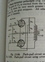
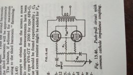
In the schematic attached, I would add a choke or resistance across both screens tied toghether and Ebb, and capactivelly decopled to cathode (floating for audio signal) so the the action may be enhanced (common cathode & screen coupling).Not really a new idea, here is something from WW2.
I tried several variations of the concept early 2017. All the results are here somewhere on DIY.
The resulting report with many measurements is here in a pdf.
Best results were got using a choke as the cathode impedance.👍
The slave tube would have a low output resistance which would reduce transformer distortion and increase damping factor, so you can boast about that! 😉What if we create a local feedback around one of output tubes similar to a paraphase splitter? I have no illusion that I'm the first but I couldn't find any mentions of this circuit.
wg_ski,
I have used chokes as CCS.
The bandwidth covers 20Hz to 20kHz.
Unless you are listening to Telarc's definitive recording of the 1812 Overture, which has 6Hz real canon signals, I would not worry about needing lower than 20Hz bandwidth.
How many of us have speakers that go down to 20Hz cleanly (at a high enough sound level that our ear's Fletcher Munson Curves do not prevent us from hearing the 20Hz sound).
Much of what we will hear from most speakers that try to reproduce 20Hz at any moderate level, not even loud, is the 2nd harmonic distortion at 40Hz, and 3rd harmonic distortion at 60Hz.
Let's check which layers of the Onion that we are peeling off first.
Just my opinions.
- Home
- Amplifiers
- Tubes / Valves
- Self splitting push-pull idea