Is there any reason why 0.12 ohms is the chosen value of the total resistance in the crc section of the power supply.
Is this a good all-round figure to go for that gives decent levels of noise filtering, and there would not be much benefit in increasing this value. The resistance value does not seem to take into acount that there maybe different levels of noise due to how clean the mains ac supply is.
Thanks
Is this a good all-round figure to go for that gives decent levels of noise filtering, and there would not be much benefit in increasing this value. The resistance value does not seem to take into acount that there maybe different levels of noise due to how clean the mains ac supply is.
Thanks
Last edited:
Hi. Increasing resistor value in CRC filter means better filtering ,but downside is higher voltage drop under load ,i assume you talking about amplifiers psu filter. Also higher resistor value means more heat . Probably designer chosed that value as compromise . Sometimes is better to replace resistor with inductor , but this depends on frequency , where this filter is used : 100/120hz rectified ripple or smps output. Inductor is more effective at higher frequencies, for low frequency you need big inductor with low DC resistance. Resistor increase filtering if compare to just capacitor after rectifier ,even low value resistor can have effect similar to increase capacitors capacity in filter.
Any advantages to increasing resistance to 0.5 ohms, using higher power resistor as well. I mean, does it get to a point to diminishing returns, that increasing resistor size gives smaller and smaller ripple reduction.
Thanks
Thanks

I think ripple will decrease proportionally ,but don't forget voltage drop. Ripple is not always so critical , most amplifiers would not produce hum at output even with high ripple present .
Thanks! I'm trying to get the ripple as low as possible. I've used a few low ripple regulated psu in my time and they do make the amplifier sound better. And I'm not too concerned about voltage drop, the power supply is slightly over rated so a small voltage drop is no problem.
So you don't think slightly increasing the resistor from 0.12 ohms to 0.5 ohms will do much
Papa seems to choose this level of filtering based on several factors. Noise filtering is most important, and the level of resistance is proportionate to the PSRR of the amplifier circuits. For example, in the no-feedback F1, F2 and BA-3/2’s, filtering is raised to 0R25. The level of voltage drop will be minimal between the two, and he uses the same transformers in the F1-2 and in the F3, 4, 5 and 6.Is there any reason why 0.12 ohms is the chosen value of the total resistance in the crc section of the power supply.
Is this a good all-round figure to go for that gives decent levels of noise filtering, and there would not be much benefit in increasing this value. The resistance value does not seem to take into acount that there maybe different levels of noise due to how clean the mains ac supply is.
Thanks
That doesn’t mean you can’t increase filtering to achieve an even cleaner sound. But I would have to agree that inductors and or increased capacitance are better choices than increasing resistor values.
I once had hum with a stock PSU.
So I built my own

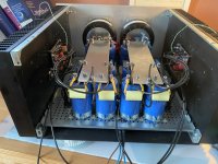
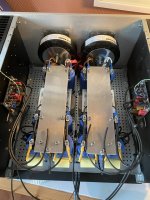
Approx 800.000uF in total, and 4x10mH inductors with a DCR of 0R160. Cannot measure any ripple at all at the rails, but maybe a scope will show something. Needless to say: complete overkill.
PS: beware: I would be more hesitant of increasing filter resistance in P/P circuits than an SE one, especially if there is a Papa CCS present. My audiophoolery tendencies makes me worry about PSU sag in P/P circuits if R is too high. But I guess that is more of a problem with class A/B circuits anyways.
Attachments
Plus it is likely not needed for the AJ which has a CCS reducing the need for bypassing.@andynor that bypass can have a bad resonance ,I will see better at the input d pcb.... btw diy fun 😉
Then I might use them to create a network for my F2J/FR combo 🙂
Btw those bypass caps are following Papas BA-3/2 PSU spec, so how bad can it be? All ears!
well putting at the imput of pbc avoid resonance by resistence of wire ,working the same as in the caps I thinks....and plus avoid gremlins enter on pcb, jumping on wire as antenna ... LOL
Will try to remove and scope it!!well putting at the imput of pbc avoid resonance by resistence of wire ,working the same as in the caps I thinks....and plus avoid gremlins enter on pcb, jumping on wire as antenna ... LOL
Papa seems to choose this level of filtering based on several factors. Noise filtering is most important, and the level of resistance is proportionate to the PSRR of the amplifier circuits. For example, in the no-feedback F1, F2 and BA-3/2’s, filtering is raised to 0R25. The level of voltage drop will be minimal between the two, and he uses the same transformers in the F1-2 and in the F3, 4, 5 and 6.
That doesn’t mean you can’t increase filtering to achieve an even cleaner sound. But I would have to agree that inductors and or increased capacitance are better choices than increasing resistor values.
I once had hum with a stock PSU.
So I built my own
Approx 800.000uF in total, and 4x10mH inductors with a DCR of 0R160. Cannot measure any ripple at all at the rails, but maybe a scope will show something. Needless to say: complete overkill.
PS: beware: I would be more hesitant of increasing filter resistance in P/P circuits than an SE one, especially if there is a Papa CCS present. My audiophoolery tendencies makes me worry about PSU sag in P/P circuits if R is too high. But I guess that is more of a problem with class A/B circuits anyways.
Thanks! i have tried a few different capacitor values and the bigger ones are reducing the ripple better than the small caps.
It's just I thought that the resistor in the crc circuit seemed a little small at 0.12 ohms, it puzzled me why it is so low, but it seems the big caps are making up for this low value. I was just musing over what the effect would be of increasing the resistor value to 0.5 ohms. Would it give super clean power. It appears from your answer : probably not.
My set up is : I have placed the transformer, bridge rectifier and smoothing caps into an abs enclosure, a metre away, as i noticed from previous projects the transformer can throw out emi radiation which lowers the amp's performance, sounds a little cleaner and more detailed without the big transformer being in the same enclosure as the amp boards.
I have 5 amp boards to build a 5-channel amp. In the abs enclosure a meter away, after the smoothing caps i have placed the 0.12 ohm resistor. If i place a final smoothing cap across the power supply of each amp board, will this form the crc filter, or does each amp board need its own resistor?
Thank you.
I would recommend you first place an extra set of smoothing caps after the filter resistors in the external PSU enclosure. Filtered, and then charged, before leaving the extrrnal PSU.My set up is : I have placed the transformer, bridge rectifier and smoothing caps into an abs enclosure, a metre away, as i noticed from previous projects the transformer can throw out emi radiation which lowers the amp's performance, sounds a little cleaner and more detailed without the big transformer being in the same enclosure as the amp boards.
I have 5 amp boards to build a 5-channel amp. In the abs enclosure a meter away, after the smoothing caps i have placed the 0.12 ohm resistor. If i place a final smoothing cap across the power supply of each amp board, will this form the crc filter, or does each amp board need its own resistor?
Thank you.
Then, in the amp enclosure, put in a set of high value low ESR caps to filter out whatever noise has been picked up between the external PSU and the amp enclosure, and also ensure easily available current close to the amp boards.
You probably know this, but carefully plan the grounding of this setup.
For inspiration, check out the XS series from Pass labs

Thanks, but isn't it the resistor that reduces the noise, the caps just shift the noise to a different frequency, so a resistor before the caps in the amp enclosure may be valid.
If you split crc filter , and put second capacitors at amplifier board , then wires from first capacitors would be in series with resistors. So its better to place resistors just before amplifier board , they will filter additionally what is picked up by long wires . Additional capacitors may be good idea ,but proper way of connecting them is important. Probably star connection for ground. Also you should use twisted wires for power , they would not pickup anything then.
If you split crc filter , and put second capacitors at amplifier board , then wires from first capacitors would be in series with resistors. So its better to place resistors just before amplifier board , they will filter additionally what is picked up by long wires . Additional capacitors may be good idea ,but proper way of connecting them is important. Probably star connection for ground. Also you should use twisted wires for power , they would not pickup anything then.
Can I place one resistor in the amplifier enclosure, then hook that up to the 5 amp boards which will have a cap across the power supply to complete the crc filter, or does each amp board need its own resistor.
Thanks!
C in PSU case
R is umbilical
C in amp case
whatever C big is
umbilical R is enough
edit: inter-channel isolation is another issue
if you want some , maybe dedicated umbilical per channel
R is umbilical
C in amp case
whatever C big is
umbilical R is enough
edit: inter-channel isolation is another issue
if you want some , maybe dedicated umbilical per channel
- Home
- Amplifiers
- Pass Labs
- 0.12 ohm resistor in PSU for Pass amp question