Hi everyone hope some one can help with my naim nap110 as it got a fault where the dc off set is showing 36v from spk terminals have checked outputs and driver both seem ok there is 37v from psu and both boards shows the 34/36v from spk terminals they both drawing 15ma and 4.2 mv bias which don't seem to adjust i must be missing some thing but not sure where
..........you mean +- 37V from psu?
if both channels show the same fault it could be psu-related ............
if both channels show the same fault it could be psu-related ............
Don't reinvent the wheel.
https://www.diyaudio.com/community/threads/naim-nap-110-amp-high-dc-offset-and-mute-channel.257524/
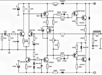
Similar circuit attached:
https://www.diyaudio.com/community/threads/naim-nap-110-amp-high-dc-offset-and-mute-channel.257524/
Similar circuit attached:
Attachments
yes there a +- 37v coming from psu to main board i do use a lightbulb in series in mains for protection but it only glows for a few seconds when i switch on as caps charge up..........you mean +- 37V from psu?
if both channels show the same fault it could be psu-related ............
attached circuit dia looks to be one for the Avondale ncc200 boardDon't reinvent the wheel.
https://www.diyaudio.com/community/threads/naim-nap-110-amp-high-dc-offset-and-mute-channel.257524/
Similar circuit attached:
You cannot expect proper operation with the light bulb. Remove it for further testing.yes there a +- 37v coming from psu to main board i do use a lightbulb in series in mains for protection but it only glows for a few seconds when i switch on as caps charge up
Said to be the Naim 140.attached circuit dia looks to be one for the Avondale ncc200 board
Member
Joined 2009
Paid Member
The amplifier design can be reverse engineered directly from images of the actual product: https://www.diyaudio.com/community/threads/tgm10-based-on-naim-by-julian-vereker.302454/
it used to protect the circuit board from causing more damage if there a short amplifier will still work for testingYou cannot expect proper operation with the light bulb. Remove it for further testing.
This doesn't convince me that you are correctly measuring the DC offset between the output terminals. Check your meter range and DC setting, make sure the input to the amp. is grounded (shorted with a resistance of say, 1-10k) and start again with nothing else connected to the amp. You say you have "37V from PSU" but you should have 2 supplies, of approximately +35VDC and also -35DC with respect to a common ground connecting wire. Are both voltages present or did you just assume we would guess what you meant?.......the dc off set is showing 36v from spk terminals............there is 37v from psu and both boards shows the 34/36v from spk terminals they both drawing 15ma and 4.2 mv bias which don't seem to adjust i must be missing some thing.......
Please indicate on a schematic, the locations where you placed the meter probes for both channels.
Last edited:

This doesn't convince me that you are correctly measuring the DC offset between the output terminals. Check your meter range and DC setting, make sure the input to the amp. is grounded (shorted with a resistance of say, 1-10k) and start again with nothing else connected to the amp. You say you have "37V from PSU" but you should have 2 supplies, of approximately +35VDC and also -35DC with respect to a common ground connecting wire. Are both voltages present or did you just assume we would guess what you meant?
Please indicate on a schematic, the locations where you placed the meter probes for both channels.
i did a new check and foundThis doesn't convince me that you are correctly measuring the DC offset between the output terminals. Check your meter range and DC setting, make sure the input to the amp. is grounded (shorted with a resistance of say, 1-10k) and start again with nothing else connected to the amp. You say you have "37V from PSU" but you should have 2 supplies, of approximately +35VDC and also -35DC with respect to a common ground connecting wire. Are both voltages present or did you just assume we would guess what you meant?
Please indicate on a schematic, the locations where you placed the meter probes for both channels.
+prob to + & neg prob to +spk shows -34.3v
- prob to - & pos prob to +spk shows 0v
& ground to + spk shows 34.3v
& power supply reading +35.9v & - 36v
It's still not clear by your description, what exactly you are doing with the meter probes or whether some measurements are made in reverse from normal sense, but you seem to verify that the +/- 35VDC supply voltages are present and assuming the speaker is disconnected, that there is 34.3VDC between the +ve and -ve output terminals. If that is true, it means you have a big problem with the output stage transistors and possibly the VAS transistor (transistor type used in NAP110 is unknown to me).i did a new check and found
+prob to + & neg prob to +spk shows -34.3v
- prob to - & pos prob to +spk shows 0v
& ground to + spk shows 34.3v
& power supply reading +35.9v & - 36v
Read Rayma's post#3, huggygoods#13 again.
Last edited:
one prob on the red speaker terminal show's -34v when other prob on ve+ or centre tap. the speakers are not connected the output & driver transistors on both boards seem to test ok when removed same as rest of transistors were removed tested ok diodes also seems okIt's still not clear by your description, what exactly you are doing with the meter probes or whether some measurements are made in reverse from normal sense, but you seem to verify that the +/- 35VDC supply voltages are present and assuming the speaker is disconnected, that there is 34.3VDC between the +ve and -ve output terminals. If that is true, it means you have a big problem with the output stage transistors and possibly the VAS transistor (transistor type used in NAP110 is unknown to me).
Read Rayma's post#3, huggygoods#13 again.
resistors & caps tested ok so i think issue could be a ground from input section causing issue on neg sideone prob on the red speaker terminal show's -34v when other prob on ve+ or centre tap. the speakers are not connected the output & driver transistors on both boards seem to test ok when removed same as rest of transistors were removed tested ok diodes also seems ok
Resistors and caps usually have nothing to do with this DC fault. If you measure 34VDC (almost the full +ve supply voltage) with the probes placed across the output terminals, that usually means there is a shorted output transistor or one of the driver transistors. First, test the voltages across each power transistor's terminals, from E-C (should be around 35V) and B-E (should be around 0.6V) , repeat with the driver transistors.
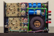
I'm not sure what type drivers were used in the original NAP 110 - they could be MJE243/253 or FZT653/753 for example but MJF's image above, shows a rebuilt amplifier with virtually every component and semiconductor replaced with new ones plus wiring and a few other changes too. Take care not to slip and short the probes to anything else in the testing process, which would likely destroy the transistors anyway. Using hook probes with your meter is a good plan, since it wouldn't be the first time that a curious owner caused damage by testing, where there was none to begin with.
I'm not sure what type drivers were used in the original NAP 110 - they could be MJE243/253 or FZT653/753 for example but MJF's image above, shows a rebuilt amplifier with virtually every component and semiconductor replaced with new ones plus wiring and a few other changes too. Take care not to slip and short the probes to anything else in the testing process, which would likely destroy the transistors anyway. Using hook probes with your meter is a good plan, since it wouldn't be the first time that a curious owner caused damage by testing, where there was none to begin with.
Apologies....I meant the long obsolete FST239/240 typesor FZT653/753 for example.
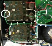
the board above is a napa 2/3 mine are napa 5/4 but yes the drivers are MJE243/253 which one board had been replaced in the past & it got neg 34v from spk posistive output. i did try a known working napa 6/3 board in amp i got the same issue that it was giving a neg 34v from the spk plus terminal them i added a extra wire from ov at caps to ov at audio input it seem to sort the issue no more neg 34v from the spk plus terminal even giving it has a ov connected from caps to rear input socket which connects to screens/shielded off wre back to board ov input amd don't have any breaks in the connection which is strange? so with a bit of research giving you mention maybe rebuilt amplifier boards i think these are nap 140 boards and as seen in pic there is a extra ov wire connectedResistors and caps usually have nothing to do with this DC fault. If you measure 34VDC (almost the full +ve supply voltage) with the probes placed across the output terminals, that usually means there is a shorted output transistor or one of the driver transistors. First, test the voltages across each power transistor's terminals, from E-C (should be around 35V) and B-E (should be around 0.6V) , repeat with the driver transistors.
I'm not sure what type drivers were used in the original NAP 110 - they could be MJE243/253 or FZT653/753 for example but MJF's image above, shows a rebuilt amplifier with virtually every component and semiconductor replaced with new ones plus wiring and a few other changes too. Take care not to slip and short the probes to anything else in the testing process, which would likely destroy the transistors anyway. Using hook probes with your meter is a good plan, since it wouldn't be the first time that a curious owner caused damage by testing, where there was none to begin with.
Attachments
- Home
- Amplifiers
- Solid State
- NAIM NAP 110 issue