So, it seems you are working on a DIY modified amplifier, not original NAP 110. From your pic above, the PSU board indeed looks like a DIY Chinese copy of that used in later versions of NAP 140 and the wiring of the supplies have probably been confused with that model in the process. I'd suggest your troubles are right there and the earlier comment by mjf that being a common fault, it is likely power supply related, may be the case. You should follow up by checking and comparing voltages associated with each channel's input transistors, for faults possibly caused by experimental changes.
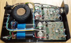
no mine is a original nap 110 the picture is of a original nap140 used as reference to show the extra ov connection on input where the 110 don't have mine was working fine and went in for a service about 7 years ago and just put away after it return first power up was last week since then as i had it for sale to find it had a issue so only thing i can think off is the boards was updated but not tested fully in the service my fault for not checking when it was returned to meSo, it seems you are working on a DIY modified amplifier, not original NAP 110. From your pic above, the PSU board indeed looks like a DIY Chinese copy of that used in later versions of NAP 140 and the wiring of the supplies have probably been confused with that model in the process. I'd suggest your troubles are right there and the earlier comment by mjf that being a common fault, it is likely power supply related, may be the case. You should follow up by checking and comparing voltages associated with each channel's input transistors, for faults possibly caused by experimental changes.
It is essential to clarify what our images actually are and what they are meant to illustrate etc. in the post they are attached to. Otherwise, it just confuses people who might assume it is an image of the OP subject. I wrote that the pic attached to mjf's pic was of a rebuilt amp. because someone had obviously replaced every component and semi, terminal etc. and fitted mounting pads to the small signal transistors - a painstaking and purely decorative effort, since those pads were originally intended as hand assembly aids for ancient TO18, TO106 etc. style semis which don't fit TO92 or E-line style pinouts anyway.
The pic does show the power supply wiring in original versions of NAP110 was all point-to-point though and the small power supply PCB was a feature of NAP140, the successor to NAP110. In the following link to Naim's forum, you see there was a wide variety of versions of NAP110/140 - an ongoing series of parts and assembly changes where nothing was quite the same from one production series to another. Note post #9 on the extra ground wire connection there: https://community.naimaudio.com/t/theres-2-version-of-nap-140-psu-design/15050.
The pic does show the power supply wiring in original versions of NAP110 was all point-to-point though and the small power supply PCB was a feature of NAP140, the successor to NAP110. In the following link to Naim's forum, you see there was a wide variety of versions of NAP110/140 - an ongoing series of parts and assembly changes where nothing was quite the same from one production series to another. Note post #9 on the extra ground wire connection there: https://community.naimaudio.com/t/theres-2-version-of-nap-140-psu-design/15050.
Last edited:
Following up on your explanation, I think you should try to take some good pics of your particular amplifier which may help us identify what should or should not be fitted in your amplifier. Naim service is very expensive but they don't make mistakes or omit soak testing. I don't presume that you went to a bona fide Naim service agent either.
Hi ian i can't make a picture of mine as the boards have been removed to allow testing of transistors off the board but this picture is identical lay out and same boards fitted with same outputs transistors etc as mine only difference's is this was listed as a 140 mine says 110 on rear both have single secondary windings on transformer which the 110 had where as i remember the 140-180 onwards had two secondary mine was from 1983
Attachments
It is recommended that you check the ZTX652 and ZTX752. It is likely that one of these two transistors is damaged. If you are lucky, one transistor will be damaged. If you are unlucky, MJE243/253 and the current amplifier tube may be damaged.
Hi zincho i remove all transistor and tested and all seem to be okIt is recommended that you check the ZTX652 and ZTX752. It is likely that one of these two transistors is damaged. If you are lucky, one transistor will be damaged. If you are unlucky, MJE243/253 and the current amplifier tube may be damaged.
Resistors can LOOK perfectly normal and be open, too. Don’t just test the transistors. And did you look at the input pair, and it’s bias resistors and current source?
i did test transistors + Resistors & diodes all seem ok the strange thing was that both boards have the same issue which i think the a OV/ground issue around the audio input sideResistors can LOOK perfectly normal and be open, too. Don’t just test the transistors. And did you look at the input pair, and it’s bias resistors and current source?
That extra ground wire is documented in the Naim forum thread I posted. It was a modification of the original product to reduce low level noise. The only question is, was your amplifier's wiring just copied later by an enthusiastic owner or by a Naim service agent who would have tested the resulting performance? A pic would tell us more.
Last edited:
You'd better publish a picture of the circuit board. According to my limited experience, you should check several parts marked in the picture. There is also MJE243+253. Then do not install the current amplifier tube. Check whether the output of the amplifier is normal. If it is normal, you can use the headset to test whether music can be played normally. If everything is normal, install the current amplifier tube for the next test.Hi zincho i remove all transistor and tested and all seem to be ok
i did check those part's but seem to be ok & felt it be more easy and less time wasted to just remove and replace all trans/caps/diodes apart from the outputs trans which all as now been replaced so after a hour of soldering and checking bias now the amp boards are back up and running okYou'd better publish a picture of the circuit board. According to my limited experience, you should check several parts marked in the picture. There is also MJE243+253. Then do not install the current amplifier tube. Check whether the output of the amplifier is normal. If it is normal, you can use the headset to test whether music can be played normally. If everything is normal, install the current amplifier tube for the next test.
View attachment 1111086
- Home
- Amplifiers
- Solid State
- NAIM NAP 110 issue