Both those coils are connected in the same polarity and would make no difference E in my drawing is different
Unfortunately it's so long ago I rewound mine I can't remember which polarity is correct.
Question.....do you think a connection such as diagram D or E or F or other connections not listed BUT always with the coils connected in series can lead to different impedance or inductance values that compromise the regularity of the motor operation?
Or all the illustrated drawings and other similar variations offer identical results?
In a nutshell it does matter which way around the inductors are wired. Inductor polarity is AC and governs the direction of the magnetic field around the inductor. In this application it matters a lot because the inductors are performing a generator function.
D and F the inductors are wired "Series Aiding" and E they are "Series Opposing". This means E the magnetic fields are opposing so the mutual inductance doesn't affect the other coil, and I suspect this is the correct wiring.
D and F the inductors are wired "Series Aiding" and E they are "Series Opposing". This means E the magnetic fields are opposing so the mutual inductance doesn't affect the other coil, and I suspect this is the correct wiring.


Finally got my set working again, thanks everyone, especially Warrjon for pointing me in the right direction.
Will post some pics soon.
Will post some pics soon.
Here's an update on some things I've been playing with.
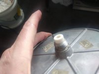
First 2 pics are a new Vesconite journal sleeve I machined to replace the damaged bronze sleeve in 1 of my SP10 motors. Looks promising as vertical platter runout is now a lot less than a stock sleeve. This one has the same tolerance as the stock sleeve and I'm going to machine another with slightly tighter tolerance.
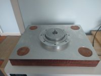
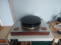
The last 2 pics are my SP!0 motor mounted in a new Permalli ground plane the holes in the top aluminium plate are for the tonearm pods.
First 2 pics are a new Vesconite journal sleeve I machined to replace the damaged bronze sleeve in 1 of my SP10 motors. Looks promising as vertical platter runout is now a lot less than a stock sleeve. This one has the same tolerance as the stock sleeve and I'm going to machine another with slightly tighter tolerance.
The last 2 pics are my SP!0 motor mounted in a new Permalli ground plane the holes in the top aluminium plate are for the tonearm pods.
Attachments
im interested in your reason for choosing Vesconite over say bearing grade torlon. cn you elaborate please?
Here is my Vesconite bearing and a Linn LP12 Cirkus bearing (PEEK) and the Vesconite is much quieter.
Completed the Permalli plinth build and transplanted the motor and tonearm from the resin/bento plinth. The new plinth is a major improvement in vibration control/damping over the resin/bento. The resin plinth is fantastic but this new one is a step up again in clarity.


Permalli/ panzerholz really is the way to go when it comes to plinths.
reading up on Vesconite,it would seem an obvious choice,i have made torlon bearings for my sony TTS-8000 and also lignum vitae,both made a noticable differenced in lowering the noise floor over the standard sony oilites they used. i've made an enquiry about buying some Vesconite as id like to try it.
reading up on Vesconite,it would seem an obvious choice,i have made torlon bearings for my sony TTS-8000 and also lignum vitae,both made a noticable differenced in lowering the noise floor over the standard sony oilites they used. i've made an enquiry about buying some Vesconite as id like to try it.
I bought some ring magnets to experiment with a non-contact passive magnet bearing. If the trial is successful I'll build a working prototype with one of my spare SP10 motors.
Just though I should add - there are 3 types of Vesconite, HILube is the one you want. I used PCD tooling to bore the journal.
very interested in this and if it will be made available ?I bought some ring magnets to experiment with a non-contact passive magnet bearing. If the trial is successful I'll build a working prototype with one of my spare SP10 motors.
From the initial experiment I need to increase magnet size significantly and this makes magnet cost nearly $1000.00 to get radial stiffness to prevent precession. So for the moment I'm going to machine a secondary Vesconite journal mounted above the motor, so the motor will have a coupling to a secondary spindle, like the Skully lathe. Then magnets will be used under the platter to reduce force on the thrust ball.
How heavy is your platter? What is the purpose of the shoulder on the platter?From the initial experiment I need to increase magnet size significantly and this makes magnet cost nearly $1000.00 to get radial stiffness to prevent precession. So for the moment I'm going to machine a secondary Vesconite journal mounted above the motor, so the motor will have a coupling to a secondary spindle, like the Skully lathe. Then magnets will be used under the platter to reduce force on the thrust ball.
Warrjon, I see on the Vesconite web site that they have a standard line of bearings designed for 3D printer applications. Not knowing the dimensions needed for the Technics motor, do you know if any of these would work?
At least for me Panzerholz and Permali (one 'l', not two) seem almost impossible to find in the USA; any pointers to a USA distributor (or Canadian?) would be appreciated.
At least for me Panzerholz and Permali (one 'l', not two) seem almost impossible to find in the USA; any pointers to a USA distributor (or Canadian?) would be appreciated.
How heavy is your platter? What is the purpose of the shoulder on the platter?
It's 9kg and the shoulder is an exact replica of the OEM platter so in my previous plinth the shoulder was level with the top of the plinth.
Warrjon, I see on the Vesconite web site that they have a standard line of bearings designed for 3D printer applications. Not knowing the dimensions needed for the Technics motor, do you know if any of these would work?
At least for me Panzerholz and Permali (one 'l', not two) seem almost impossible to find in the USA; any pointers to a USA distributor (or Canadian?) would be appreciated.
I bought Hilube 15mm OD 8mm ID and machined them myself.
OD is 12.05mm and ID was machined after the bush was pressed in. I experimented with different ID's prior to the pressing in but the crush was unpredictable.
I think Picawood is available in the US and is a similar densified wood.
Here is the latest Vesconite bearing, this video there is no stator in the motor. Vertical runout is slightly better than OEM at a TIR of 6 microns and bearing noise is below the noise floor of the Focusrite.
nice work,what would you say is an exceptable level of run out?
i have my vesconite now,really impressed with the service/delivery time. i'll turn some at the weekend.
i have my vesconite now,really impressed with the service/delivery time. i'll turn some at the weekend.
In a hydrodynamic journal there will always be runout because the journal needs clearance and the SP10mk2 journal is small at 9/32 so angular velocity is slow.
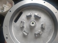
The rotor in last video would show a lot less runout if I modified the rotor like my daily driver SP!0. Where I bored the rotor, pressed in a brass bush bored the bush then pressed in the spindle, next I clocked the spindle in the 4 jaw and took a very light cut off the platter mounting face to true up the mounting face to the spindle. This reduced runout on my daily so doing this on the rotor in the last video would most likely reduce runout by another few microns.
This is a pic of the rotor in my daily SP10 you can see the brass bush. The spindle is a press fit no more glued in spindle.
Last edited:
- Home
- Source & Line
- Analogue Source
- The Incredible Technics SP-10 Thread