I no sooner cast my resin/bento plinth than Bon and warrjon brought up the point that it would be way better to ditch the chassis and just have a motor drive plinth. Now I am ready to undertake that project.
Note: I have 2 SP-10's so I am not without my favorite TT.
This will be a Permalli/Panzerholz build.
I am looking for guidance on some basic questions. This will be set up with 2 tone arms.
1. Any comments on planform size? It looks like it will be in the neighborhood of 19.5in square. It is dependent on the tone arm pivot to spindle distance but that can change with time.
2. Any reason not to be flexible on the thickness? A little extra thick doesn't seem to be a downside. I am thinking of using 1in thick material. Less laminations.
3. It seems the best way to get started would be to leave every thing else in the chassis and just hook the motor drive to that. Open to suggestions.
Other?
Thanks,
Don
Hey Don,
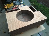
I used Panzerholz in 1” x 6 layers for my MK3, no complaints on the thickness, however PH is a beast to cut – if you can I recommend using a router in many many shallow passes. If you’re nude mounting the motor directly no chassis, assuming you’re using an MK3? If you’re nude mounting an MK2 let me know how you go, because I know it’s much more complicated and I’d love to see your application.
I used Panzerholz in 1” x 6 layers for my MK3, no complaints on the thickness, however PH is a beast to cut – if you can I recommend using a router in many many shallow passes. If you’re nude mounting the motor directly no chassis, assuming you’re using an MK3? If you’re nude mounting an MK2 let me know how you go, because I know it’s much more complicated and I’d love to see your application.
Andrew, I am nude mounting the MK2. I will keep all posted. Thank you for response. I can router cut it. Tedious but a good way for diy to get a good cut. Thanks for suggestion. What was your source for PH.Hey Don,
I used Panzerholz in 1” x 6 layers for my MK3, no complaints on the thickness, however PH is a beast to cut – if you can I recommend using a router in many many shallow passes. If you’re nude mounting the motor directly no chassis, assuming you’re using an MK3? If you’re nude mounting an MK2 let me know how you go, because I know it’s much more complicated and I’d love to see your application.
Do you have a pic or post number for your build. I have read this thread start to finish but it is a blur. Tend to focus on task at hand.
Regards,
Don
Nice one. I actually did an MK2 as my practice round, just in Baltic Birch, but I’ve been thinking about going for nude mounting that one now and fixing my mistakes (only visible to me lol).Andrew, I am nude mounting the MK2. I will keep all posted. Thank you for response. I can router cut it. Tedious but a good way for diy to get a good cut. Thanks for suggestion. What was your source for PH.
Do you have a pic or post number for your build. I have read this thread start to finish but it is a blur. Tend to focus on task at hand.
Regards,
Don
My MK3 you can see here: https://www.audiogon.com/systems/10509
My Panzerholz source was BKB Industrial in Canada. Shipping is expensive as they normally pallet this stuff BUT what I did was give them my cut list and the did the bigger rips before shipping, this allowed them to package it without a pallet and was also a big time (and blade) saver. Happy to share my experiences anytime.
Attachments
-
 944C986D-899D-4C09-994E-256D0CFA3B54.jpeg552.9 KB · Views: 176
 -
 A389FD77-0628-468D-ACB3-588B48D51CDB.jpeg551.5 KB · Views: 132
 -
 8135E369-45B2-45EC-AD87-32E43D94A75C.jpeg689 KB · Views: 127
 -
 7F0C230C-625C-40ED-BD18-07355555EECA.jpeg765.5 KB · Views: 130
 -
 CE1B84B9-64B9-4373-B9F9-B145F7A26D1F.jpeg448.9 KB · Views: 124
 -
 574C6695-E90E-4471-B659-E966BCE0CDC5.jpeg207.9 KB · Views: 126
 -
 C131C25A-328A-4F5E-B03C-674FC966390A.jpeg896.2 KB · Views: 129
 -
 C5A7D7A7-FBBB-4DA7-9359-B428729AD90B.jpeg217.7 KB · Views: 124
 -
 6C1EFFEA-3439-4529-A6B0-D8767CEC1B0D.jpeg723.2 KB · Views: 136
 -
 B8FDC411-E511-4AFD-859D-B3213058500A.jpeg917.8 KB · Views: 163
 -
 639FCF91-3E0D-4BC8-8BAA-1713DEF6AB15.jpeg879.9 KB · Views: 142
 -
 8336DB93-F0C5-405F-87BD-A49E88C5F169.jpeg1,003.6 KB · Views: 131
 -
 2280E232-4FF2-43BB-B021-E3BB2314687B.jpeg568.6 KB · Views: 133
 -
 F1F2DC29-4EA7-4EA8-8F3F-6E5FE276081E.jpeg266.6 KB · Views: 127
 -
 5A95817C-8C4F-4FF7-990C-C91A60AC2FA3.jpeg368.4 KB · Views: 138
 -
 BBDE11AB-E507-47C4-B342-692A0167B0C3.jpeg496.9 KB · Views: 144
 -
 BFEE8E7E-5AC4-49CF-BA6D-BBA09C4E6F19.jpeg462.4 KB · Views: 141
 -
 BAAA0B26-EC6C-46C9-8EA0-5A3F041CFC08.jpeg378.6 KB · Views: 169
 -
 A5789780-8723-440A-BDFA-173DB235AB9B.jpeg543.2 KB · Views: 186

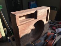
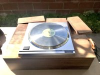
I showed a photo diary of how this went for me with a bento/resin plinth in posts #1488, 1489, 1528. The Kaneta style SP10 with Acetal/POM/Delrin platter is my daily drive and the best TT to reside in my system. In principle this would be simple with sheet material like Panzerholz/Permali but the cutting/machining/routing is a P.I.T.A. I knocked up a plywood test plinth in a couple of hours.3. It seems the best way to get started would be to leave every thing else in the chassis and just hook the motor drive to that. Open to suggestions.
Andrew, great job! Impressive detail work. A lot of detail. Hard to do so congratulations Lots of inside rounds. Inspirational. And, getting the Tone Arm board match is beyond.Nice one. I actually did an MK2 as my practice round, just in Baltic Birch, but I’ve been thinking about going for nude mounting that one now and fixing my mistakes (only visible to me lol).
My MK3 you can see here: https://www.audiogon.com/systems/10509
My Panzerholz source was BKB Industrial in Canada. Shipping is expensive as they normally pallet this stuff BUT what I did was give them my cut list and the did the bigger rips before shipping, this allowed them to package it without a pallet and was also a big time (and blade) saver. Happy to share my experiences anytime.
Whatever is the size of planform? Glad you responded. Thanks.
Don
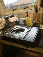
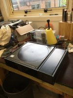
Bon, the control box looks like a fairly tight fit. Any worries about heat from the motor drive transistors. Any heat sinking?I showed a photo diary of how this went for me with a bento/resin plinth in posts #1488, 1489, 1528. The Kaneta style SP10 with Acetal/POM/Delrin platter is my daily drive and the best TT to reside in my system. In principle this would be simple with sheet material like Panzerholz/Permali but the cutting/machining/routing is a P.I.T.A. I knocked up a plywood test plinth in a couple of hours.
Thanks,
Don
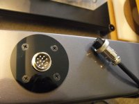
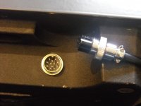
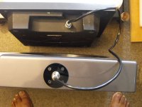
I don't have metal fabrication facilities or skills, but I am handy with timber etc. So my control box is made from 10mm black acrylic. The complete chassis/minus motor is a friction fit with hard foam rubber wedges into the box section to the left. The power supply is in the open back section to the right of a solid partition. There is no heat dissipation concerns with the control electronics but the power supply can get warm which is why I left that section open at the rear. Also it makes the power supply back panel plug easily accessible. I rebated precise recesses for the power supply feet to drop in snug. The dimensions and clearances are chosen so that the screw down top holds everything tightlyly in place. The chassis and power supply are a simple lift out if required. The umbilical joining the motor to the control box is a 12-pin aviation connector from eBay.Bon, the control box looks like a fairly tight fit. Any worries about heat from the motor drive transistors. Any heat sinking?
Thanks,
Don
Attachments
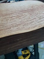
When I did my Permalli plinth my Dewalt table saw stalled while trying to trim the 60mm thick Permalli. I ended up milling the faces flat and edges. The Permalli is not flat so I would suggest having the supplier plane the sheets flat.
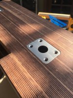
Removing the mk2 motor you will need to change the connector on the motor wiring. Use a 12pin round connector (like @Bon shows) and swap 1 wire at a time, be careful as there are 2 RED and Grey wires that you need to pay attention to what pin they go to, these CAN NOT be swapped.
Removing the mk2 motor you will need to change the connector on the motor wiring. Use a 12pin round connector (like @Bon shows) and swap 1 wire at a time, be careful as there are 2 RED and Grey wires that you need to pay attention to what pin they go to, these CAN NOT be swapped.
Attachments
Don
I have been successful with my being a advocate of the idea to experience a Kaneta Styled SP10 Mkii.
In early 2023, there should be a functioning TT. The Set Up is ready, with a few electronic items to outstanding to be troubleshot.
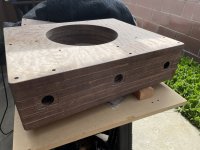
To let you know, The Motor is set into a 25mm Board Thickness - B25 - Cross Grain P'holz - as the New Chassis, which is designed to take two tone arms.
Originally the chassis was to be produced from my owned 75mm Thick Board Permali. I was promoting the idea to have the Cast Metal Motor Bowl and Spindle Housing Extension encapsulated in a very tight fitting rebated chassis, as a measure to substantially reduce flexion/eccentric rotation at the Sump End of the Spindle Bearing Housing, as a result of rigidly locking it in place..
The New P'holz Chassis is born from the results the producer has had from the use of P'holz on their own SP10 Mkii and how careful usage of it as designed parts has created a impression that has a very high appraisal.
The New Chassis is to be trialed as a Single Board Chassis Only and later have additional parts produced from P'holz added to the underside to be used to rigidly lock the entirety of the Bowl and Bearing Housing in place.
The Two Tonearm Method is going to be quite interesting, as I have donated a SME IV and a Low Hours used Ortofon Kontrapunkt b Cart, to be used in conjunction with the TT owners Tonearms and Low Hours usage Kb' Cart.
The Producer of the Kaneta Style SP10 Mkii, has there own Built from scratch Tonearm, along with other owned and respected Tonearm Models. This New Chassis is the Design to enable A/B Comparisons of other Tonearms to see how they compare to the Built from Scratch Arm.
After approx' 2 Years of making inroads to stimulate others to what is my view a very good idea, it is now looking that during 2023, there is be presented a few interesting moments to experience Vinyl replays in a manner that has had my attention for quite some time.
I have been successful with my being a advocate of the idea to experience a Kaneta Styled SP10 Mkii.
In early 2023, there should be a functioning TT. The Set Up is ready, with a few electronic items to outstanding to be troubleshot.
To let you know, The Motor is set into a 25mm Board Thickness - B25 - Cross Grain P'holz - as the New Chassis, which is designed to take two tone arms.
Originally the chassis was to be produced from my owned 75mm Thick Board Permali. I was promoting the idea to have the Cast Metal Motor Bowl and Spindle Housing Extension encapsulated in a very tight fitting rebated chassis, as a measure to substantially reduce flexion/eccentric rotation at the Sump End of the Spindle Bearing Housing, as a result of rigidly locking it in place..
The New P'holz Chassis is born from the results the producer has had from the use of P'holz on their own SP10 Mkii and how careful usage of it as designed parts has created a impression that has a very high appraisal.
The New Chassis is to be trialed as a Single Board Chassis Only and later have additional parts produced from P'holz added to the underside to be used to rigidly lock the entirety of the Bowl and Bearing Housing in place.
The Two Tonearm Method is going to be quite interesting, as I have donated a SME IV and a Low Hours used Ortofon Kontrapunkt b Cart, to be used in conjunction with the TT owners Tonearms and Low Hours usage Kb' Cart.
The Producer of the Kaneta Style SP10 Mkii, has there own Built from scratch Tonearm, along with other owned and respected Tonearm Models. This New Chassis is the Design to enable A/B Comparisons of other Tonearms to see how they compare to the Built from Scratch Arm.
After approx' 2 Years of making inroads to stimulate others to what is my view a very good idea, it is now looking that during 2023, there is be presented a few interesting moments to experience Vinyl replays in a manner that has had my attention for quite some time.
JohnnoG, thanks for the reply. Who is your P'holz source. Also, what are the planform dimensions of your 2 tonearm plinth. Hard to change once you start down that path. Mine will also be 2 tonearm.Don
I have been successful with my being a advocate of the idea to experience a Kaneta Styled SP10 Mkii.
In early 2023, there should be a functioning TT. The Set Up is ready, with a few electronic items to outstanding to be troubleshot.
To let you know, The Motor is set into a 25mm Board Thickness - B25 - Cross Grain P'holz - as the New Chassis, which is designed to take two tone arms.
Originally the chassis was to be produced from my owned 75mm Thick Board Permali. I was promoting the idea to have the Cast Metal Motor Bowl and Spindle Housing Extension encapsulated in a very tight fitting rebated chassis, as a measure to substantially reduce flexion/eccentric rotation at the Sump End of the Spindle Bearing Housing, as a result of rigidly locking it in place..
The New P'holz Chassis is born from the results the producer has had from the use of P'holz on their own SP10 Mkii and how careful usage of it as designed parts has created a impression that has a very high appraisal.
The New Chassis is to be trialed as a Single Board Chassis Only and later have additional parts produced from P'holz added to the underside to be used to rigidly lock the entirety of the Bowl and Bearing Housing in place.
The Two Tonearm Method is going to be quite interesting, as I have donated a SME IV and a Low Hours used Ortofon Kontrapunkt b Cart, to be used in conjunction with the TT owners Tonearms and Low Hours usage Kb' Cart.
The Producer of the Kaneta Style SP10 Mkii, has there own Built from scratch Tonearm, along with other owned and respected Tonearm Models. This New Chassis is the Design to enable A/B Comparisons of other Tonearms to see how they compare to the Built from Scratch Arm.
After approx' 2 Years of making inroads to stimulate others to what is my view a very good idea, it is now looking that during 2023, there is be presented a few interesting moments to experience Vinyl replays in a manner that has had my attention for quite some time.
Keep us posted. Any pics?
Definitely merit to locking down the sump end bearing housing down. warrjon did that.
R,
Don
Super valid and super helpful. Thank you.When I did my Permalli plinth my Dewalt table saw stalled while trying to trim the 60mm thick Permalli. I ended up milling the faces flat and edges. The Permalli is not flat so I would suggest having the supplier plane the sheets flat.
Removing the mk2 motor you will need to change the connector on the motor wiring. Use a 12pin round connector (like @Bon shows) and swap 1 wire at a time, be careful as there are 2 RED and Grey wires that you need to pay attention to what pin they go to, these CAN NOT be swapped.
Due to all the detail in one of these I might be mocking up a few things along the way. I learned on the R/B plinth that you get heavily invested and it's a little nerve racking avoiding mistakes you can't reverse.
Don
Thanks Bon. Pics also a big help. I'm fired up about the plinth but not so much about the control box.🙁I don't have metal fabrication facilities or skills, but I am handy with timber etc. So my control box is made from 10mm black acrylic. The complete chassis/minus motor is a friction fit with hard foam rubber wedges into the box section to the left. The power supply is in the open back section to the right of a solid partition. There is no heat dissipation concerns with the control electronics but the power supply can get warm which is why I left that section open at the rear. Also it makes the power supply back panel plug easily accessible. I rebated precise recesses for the power supply feet to drop in snug. The dimensions and clearances are chosen so that the screw down top holds everything tightlyly in place. The chassis and power supply are a simple lift out if required. The umbilical joining the motor to the control box is a 12-pin aviation connector from eBay.
Don
Thanks Don! Was a long project during pandemic. The arm boards I can measure for you when home. They’re not identical
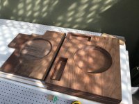
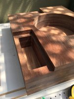
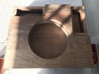
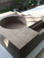
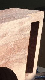
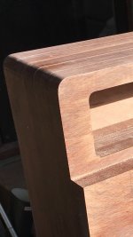
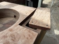
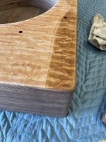
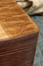
I knew in advance I was using an FR-66s so that helped with the arm boards. I designed the cuts in computer just using a vector app (since I’m a graphic designer, but most people would use CAD). I wanted the platter to be horizontally centered, so I basically used the SP-10 measurements an started from that center point, measuring pivot to spindle at an angle the gave my tone-arm mounting hole a centered position on the arm board. Pretty standard in theory I guess, but doing that beforehand in the computer determined my arm board cuts. They do match, as they’re made of the same top layer of PH, but in reality they’re not the same pieces cut out. I could have probably done that (disguising imperfections at the horn/vert cut intersection once veneered) but I wanted a rounded inner corner so I made the atm boards after, using leftover pieces. That was definitely not easy. If I had an industrial belt sander it’d have been faster, but I was in no rush. I’m general, the router is key, and the orbital sander is 2nd key. I basically taught myself everything as I went (heavily leaning on Russ at Layers of Beauty for advice) so please forgive me if anyone has more professional tips.
Thanks Don, was a lovely project over the lockdown, alongside a few amps whatnot!Andrew, great job! Impressive detail work. A lot of detail. Hard to do so congratulations Lots of inside rounds. Inspirational. And, getting the Tone Arm board match is beyond.
Whatever is the size of planform? Glad you responded. Thanks.
Don
I knew in advance I was using an FR-66s so that helped with the arm boards. I designed the cuts in computer just using a vector app (since I’m a graphic designer, but most people would use CAD). I wanted the platter to be horizontally centered, so I basically used the SP-10 measurements an started from that center point, measuring pivot to spindle at an angle the gave my tone-arm mounting hole a centered position on the arm board. Pretty standard in theory I guess, but doing that beforehand in the computer determined my arm board cuts. They do match, as they’re made of the same top layer of PH, but in reality they’re not the same pieces cut out. I could have probably done that (disguising imperfections at the horn/vert cut intersection once veneered) but I wanted a rounded inner corner so I made the atm boards after, using leftover pieces. That was definitely not easy. If I had an industrial belt sander it’d have been faster, but I was in no rush. I’m general, the router is key, and the orbital sander is 2nd key. I basically taught myself everything as I went (heavily leaning on Russ at Layers of Beauty for advice) so please forgive me if anyone has more professional tips.
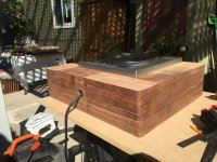
That's a nice looking plinth Andrew.Nice one. I actually did an MK2 as my practice round, just in Baltic Birch, but I’ve been thinking about going for nude mounting that one now and fixing my mistakes (only visible to me lol).
My MK3 you can see here: https://www.audiogon.com/systems/10509
My Panzerholz source was BKB Industrial in Canada. Shipping is expensive as they normally pallet this stuff BUT what I did was give them my cut list and the did the bigger rips before shipping, this allowed them to package it without a pallet and was also a big time (and blade) saver. Happy to share my experiences anytime.
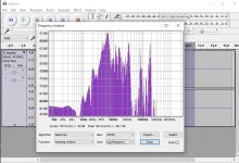
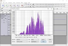
When I built the Permalli plinth I was not expecting the improvement over the R/B that I had. To ensure the only variable was the plinth I removed the motor from the R/B and installed it and the platter in the Permalli plinth.
I performed impact testing on both the R/B before removing the motor/platter and the Permalli. I placed the stylus on a stationary LP and and tapped the plinth. Here are the plots, the R/B peak at 68Hz is -52dB, Permalli peak at 66Hz is -59dB, -7dB is 100% improvement over the R/B. Above 100Hz the Permalli is significantly better, in the 360Hz region the improvement is 20dB.
Attachments
Thanks Bon. Pics also a big help. I'm fired up about the plinth but not so much about the control box.🙁
Don
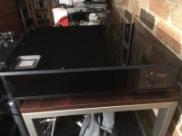
The SP10 electronics will fit in a 2U rack enclosure with the power supply remaining separate. I have not done this yet as I am looking at building my own microprocessor based controller for the mk2 motor.
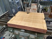
I'm also well down the road with the build of an inverted bearing SP10mk2 motor. Here is the platter roughed out.
in the end, viewing all these processes and modifications of the original Sp 10 nothing will remain. 🙁
Yes it will. It will always be an SP-10.in the end, viewing all these processes and modifications of the original Sp 10 nothing will remain. 🙁
 Even better. THE NEW AND IMPROVED SP-10.🙂🙂
"Do you have the old model or the New and Improved model."
Point well taken.
I feel like I'm chasing a moving target. How is the Vesconite bearing doing?The SP10 electronics will fit in a 2U rack enclosure with the power supply remaining separate. I have not done this yet as I am looking at building my own microprocessor based controller for the mk2 motor.
I'm also well down the road with the build of an inverted bearing SP10mk2 motor. Here is the platter roughed out.
View attachment 1123292
in the end, viewing all these processes and modifications of the original Sp 10 nothing will remain. 🙁
But better sound quality.
Technics did the best job they could with the technology of the time. A stock is good, but when modified it becomes a TT capable of playing with the big boys over $100k.
Technics made 1000's of them so they are plentiful although now the price is rising.
- Home
- Source & Line
- Analogue Source
- The Incredible Technics SP-10 Thread