Some on the Klipsch concept bi transformer crossover schematic can be find here
https://www.tubecad.com/2020/07/blog0509.htm
at the end of page...
It was published in the book
Handbook of Industrial Electronics, by Markus and Zeluff
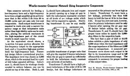
The full article appeared in the November 1945 issue of Electronics magazine.
.
.
https://www.tubecad.com/2020/07/blog0509.htm
at the end of page...
It was published in the book
Handbook of Industrial Electronics, by Markus and Zeluff
The full article appeared in the November 1945 issue of Electronics magazine.
.
.
Attachments


High order crossover, so a little complicated and compromised. I prefer broadband drivers with shallow XO. Less phase shift and less distortion from multiple capacitors and inductors.
what is shallow XO 6db/oct?
These are 12db/oct for LF and sort of 24db/oct for HF (probably horn unit with compression driver...)
So it is not higher ordrer for LF it is just one element more from 6db/oct
I could not see how this additional passive element producing significantly additional "distortion" as factor in the whole system...
And 24db/oct is good choice for the HF High preassure high db level, to cut out LF part coming into the Horn that can damage the driver.
Yes, 6 dB/oct.what is shallow XO 6db/oct?
I know that in speaker design most people believe that inductors and capacitors don't introduce sound coloration. But in my experience they do, especially capacitors and iron core inductors. I try to design the whole system to avoid them to the extent practically possible, so a pileup of these elements in a crossover is something I would like to avoid, too.I could not see how this additional passive element producing significantly additional "distortion" as factor in the whole system...
That is not my situation. I don't use high pressure high dB in a horn. The drivers I described previously have working frequencies of 60-8,000 (mid) and 200-20,000 (high), so can be crossed first order at 1,000 Hz with safety and low distortion.And 24db/oct is good choice for the HF High preassure high db level, to cut out LF part coming into the Horn that can damage the driver.
I understand that Klipsch had no choice with his compression horn-loaded tweeter, but now after 77 years we luckily have better tweeters than that.
Last edited:
This thread is exploring the idea of no-feedback pentode amplifier as a simple way of speaker current drive. So, no-NFB is a feature here, not a bug. I am attempting to make a no-NFB pentode amplifier with best linearity, with distortion levels close to those of good triode amplifiers.
Late to the party but perhaps worth recommending a read of Frank Blöhbaum's "A New Low-Noise Circuit Approach for Pentodes" in Linear Audio Vol 0 . His harmonic distortion plots look like they might fit your bill nicely.
I have used Frank's circuit with excellent results for voltage amplification (highly recommended), so now we need something just as sweet for the output stage, where Frank's BestPentode topology cannot be so easily applied.Late to the party but perhaps worth recommending a read of Frank Blöhbaum's "A New Low-Noise Circuit Approach for Pentodes" in Linear Audio Vol 0 . His harmonic distortion plots look like they might fit your bill nicely.
I didn't notice that "easy" was one of the necessary design considerations. Are you thinking the voltage limits of the BP transistor?be so easily applied.
Nevertheless, it could be a good start for the input/driver pentode.
Might even be pretty useful in sser2's intended application, being only limited by a minimum dynamic anode of G2 voltage plus the overhead voltage of the G2 cascoding stage (might need steering diodes, etc. and/or a vacuum valve in place of the semi-con, for safety at high voltages). For transmitting pentodes, especially the modern oxide cathode ones, or sweep tubes, G2 DC voltage might be low enough to not be a big limitation on anode minimum dynamic voltage swing. Cool idea anyway.I have used Frank's circuit with excellent results for voltage amplification (highly recommended), so now we need something just as sweet for the output stage, where Frank's BestPentode topology cannot be so easily applied.
All good fortune,
Chris
Thanks for the input. Ordered a copy, will see what it is about.Late to the party but perhaps worth recommending a read of Frank Blöhbaum's "A New Low-Noise Circuit Approach for Pentodes" in Linear Audio Vol 0 . His harmonic distortion plots look like they might fit your bill nicely.
6W6GT?sweep tubes, G2 DC voltage might be low enough to not be a big limitation on anode minimum dynamic voltage swing. Cool idea anyway.
Yes to both points.Are you thinking the voltage limits of the BP transistor?
Nevertheless, it could be a good start for the input/driver pentode.
6W6 would be fine as low voltage, low power tube. One of my top choices is 6146 (actually one of its filamentous cathode versions). Max Ua=750 V, Ug2=250 V. Max audio output power in PP AB1 is at Ug2=200 V.6W6GT?
Many power RF beam power tubes had medium voltage screens, but the plates were capable of very large voltage.
Those high impedance plates typically worked into narrow band very high-Q resonant Pi CLC networks. The input capacitance was low, and the output capacitance was high, to match the high impedance plate to the low impedance 50 Ohm output of the transmitter.
Note: RF narrow band, such as 1 MHz bandwidth at 100 MHz (a medium Q of 100 covering 1% of the carrier frequency).
Audio: 20Hz - 20kHz, not narrowband, no carrier.
Audio output transformers are generally not narrow band very high-Q resonators, so it is often harder to use the RF tube to get the same performance level out of an audio amplifier that uses the same RF tube (many do not want to listen to very narrowband audio).
Interesting. 6146 data sheet has tables for audio use in PP AB1 and AB2. This tube is very popular among hams, as there are commercial transmitters using it. Audio data is provided so that same tube can be used as modulator and as RF amplifier.Many power RF beam power tubes had medium voltage screens, but the plates were capable of very large voltage.
Those high impedance plates typically worked into narrow band very high-Q resonant Pi CLC networks. The input capacitance was low, and the output capacitance was high, to match the high impedance plate to the low impedance 50 Ohm output of the transmitter.
Note: RF narrow band, such as 1 MHz bandwidth at 100 MHz (a medium Q of 100 covering 1% of the carrier frequency).
Audio: 20Hz - 20kHz, not narrowband, no carrier.
Audio output transformers are generally not narrow band very high-Q resonators, so it is often harder to use the RF tube to get the same performance level out of an audio amplifier that uses the same RF tube (many do not want to listen to very narrowband audio).
There was a commercial guitar amplifier using 6146, notoriously prone to blowing up because output tubes (connected in parallel!) were taken to their limits.
sser2,
Yes, there are numerous tubes that are used for both RF and push pull audio (for modulator service, and for Hi Fi amplifiers).
807; 845 (audio and medium frequency RF); and many more.
There are only a few things worse than parallel tubes that are taken to their limits . . .
especially when they are additionally assaulted because they are not Individually Biased.
And sometimes you see a g1 grid return resistor that are low enough resistance for one tube, but not for 2, 3, or 4 parallel tubes. Ouch!
I once built a single ended amplifier using an Eimac 4-65A true Tetrode.
I grounded the plate, and used the screen for the plate (screen 10 Watt dissipation, the same as a type 45 Triode).
Someday, perhaps I will use a higher B+ voltage, and use the plate this time.
What a pretty tube!
I would really like to see some discussion and info on how to do this, not necessarily infinite impedance but High Z out with lower distortion. It might be a way to make use of today's over damped speaker drivers in sealed or IB enclosures.Well, if you really want near-ideal, linear current drive, use current-derived negative feedback.
Ohh wait, that violates the 1st commandment - Thou shalt not use feedback. Sorry, crappy current drive it is then.
Jan
Anatoly just stated that current feedback can be applied to increase output impedance. There is no practical schematic.Something from Wavebourn to kick it off.
Maybe Jan can come up with something?
- Home
- Amplifiers
- Tubes / Valves
- No-feedback pentode amplifier