I expect self-resonance above 100 kHz. Didn't measure it yet.So what freq range would that have? Or is it for HF (measurement?) use?
I guess for LF (20-100Hz) you'd still need a mountain of metal.
Jan
LF transformer is using 3 kVA toroid core. About 10 kg. Primary is 6 K plate-to-plate for parallel 6BG6GA Sylvania (a.k.a. super-6BG6), 300 H. HF transformer on top for comparison.
Last edited:
Unlikely. This is 100 dB efficient speaker that requires only a small fraction of a watt for normal listening level.the VC can drive it out of that region and that is very nonlinear
Transformers: the ferro magnetic core adds hysteresis distortion. Would be lovely to add feedback around them
Good ol' 807. Less than 2% THD in AB1 PP at 80 W 750 V, 12 K. Good number of distortion graphs for various conditions in the data sheet. Can see the tendency of distortion decreasing as plate voltage increases.Re: low distortion power pentodes, do they even exist?
That is true. But some magnetic materials are better than others. Regular silicon steel is the worst, grain-oriented is better. But 80% nickel and some modern amorphous stuff have very low hysteresis, so that seen on the same scale as silicon steel, the B-H curve looks like straight line.Transformers: the ferro magnetic core adds hysteresis distortion. Would be lovely to add feedback around them
As discussed earlier in this thread and elsewhere, negative feedback around a broadband transformer is problematic. Transformer introduces phase shifts due to its leakage inductance and winding capacitance, which may destabilize the closed loop. A transformer inside NFB loop must be of good quality (low leakage inductance and winding capacitance), but even then only moderate amount of feedback can be applied.
This thread is about pentode amplifier deliberately not using feedback - to make it high output impedance for the purpose of speaker current drive.

do you have some pointers to the low hysteresis materials? would be attractive for speaker drivers tooThat is true. But some magnetic materials are better than others. Regular silicon steel is the worst, grain-oriented is better. But 80% nickel and some modern amorphous stuff have very low hysteresis, so that seen on the same scale as silicon steel, the B-H curve looks like straight line.
As discussed earlier in this thread and elsewhere, negative feedback around a broadband transformer is problematic. Transformer introduces phase shifts due to its leakage inductance and winding capacitance, which may destabilize the closed loop. A transformer inside NFB loop must be of good quality (low leakage inductance and winding capacitance), but even then only moderate amount of feedback can be applied.
This thread is about pentode amplifier deliberately not using feedback - to make it high output impedance for the purpose of speaker current drive.
Yes, I was thinking of that too, but it may be not practical. The examples are 80% Ni permalloy and various Fe-based amorphous or nanocrystalline materials such as Metglas, Vitroperm, Finemet etc. Permalloy has to be annealed in hydrogen atmosphere to attain the lowest hysteresis, which can be done with tape or thin laminations, but not with a solid chunk of metal needed to make a pole piece. Amorphous is made by extremely rapid cooling of molten metal, so again it is good for thin film, but not for solid piece.do you have some pointers to the low hysteresis materials? would be attractive for speaker drivers too
Amen. Can be done this way or that way. No-feedback is simpler.Well, if you really want near-ideal, linear current drive, use current-derived negative feedback.
Ohh wait, that violates the 1st commandment - Thou shalt not use feedback. Sorry, crappy current drive it is then.
Jan
Practically not very crappy. There is no need for infinite impedance for speaker current drive. Something like 30 Ohms for a 8 Ohm speaker should be good.
Last edited:
HiI'm not a transformer expert, but is it 'easier' to design an OPT for say 20Hz to 100Hz and another one from 100Hz to 20kHz, instead of a single one for 20Hz to 20kHz?
Has that ever been tried?
Jan
Yes Paul W Klipsch published an article about exact topic decades ago. Maybe even holds patent?
He proposed this concept as crossover.
I will try to dig this paper in hd
My friend Iain is building a 1945 PWK amplifier to be used at the museum, to drive the Klipschorn S/N 1. Tonight we fired it up, in a very open unfinished state, and adjusted the value of screen dropping resistor, etc. It incorporates a 500Hz crossover at 5000 Ohms, between the output valve anodes and the separate, frequency-specialized, OPTs, designed and donated by Dave Slagle.
https://www.itishifi.com/hifi/e6t9cq21j46qzfsz2prvb2e33xy3u4
https://www.itishifi.com/hifi/pwk-amplifier-p3
All good fortune,
Chris
https://www.itishifi.com/hifi/e6t9cq21j46qzfsz2prvb2e33xy3u4
https://www.itishifi.com/hifi/pwk-amplifier-p3
All good fortune,
Chris
Last edited:
That's very interesting! I'll meet Dave later this week at the European Triode Festival - I'll pump him on it!
Jan
Jan
Hi
It reminds me to Super Triode Class A amplifier designs.
Mostly SE and basically with pentode as power tube
some of the examples @
https://www.ne.jp/asahi/evo/amp/guide.htm
...
with KT90
https://www.ne.jp/asahi/evo/amp/kt90/report.htm
")
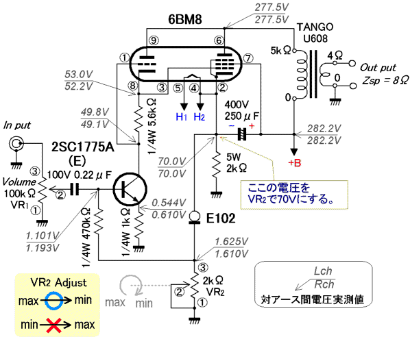
with 6BM8
")
Last edited:
The very earliest Klipschorns were available in type A, with speaker level crossover, or type B, with an amazingly dangerous 3-pin input connector to be fed from one's (presumably DIY) amplifier's (assumed to be push-pull 2A3s, because what kind of heathen would use anything else?) anodes and B+. Yikes, but men were men in the old days, having survived the war. Type B had the 500Hz 5000 Ohm crossover and OPTs that Dave Slagle designed, built and donated for us, built-in. We've moved that stuff into the amplifier chassis for obvious safety reasons.
Please tell him thanks again, his stuff worked great!
Chris
Please tell him thanks again, his stuff worked great!
Chris
some links
maybe to was before...
https://www.pearl-hifi.com/06_Lit_Archive/02_PEARL_Arch/Vol_09/Sec_32/2500_Beam_Power_Tubes.pdf
.
another for OT
https://audioxpress.com/article/you-can-diy-vanderveen-trans-se10-secrets
maybe to was before...
https://www.pearl-hifi.com/06_Lit_Archive/02_PEARL_Arch/Vol_09/Sec_32/2500_Beam_Power_Tubes.pdf
.
another for OT
https://audioxpress.com/article/you-can-diy-vanderveen-trans-se10-secrets
Parallel crossover architecture works well with low impedance triode output such as PWK design. I think high impedance pentode output works better with serial crossover architecture.Biamp is more complicated. Transformer-level XO is just extra HF transformer and one capacitor. Result is same as biamp.
Better get that second cup of coffee, and come back after beating your head against the problem for a while. You are going to end up with a non-monotonic impedance curve, and that’s exactly what gives current drive fits (As far as keeping a correctable flat response).Biamp is more complicated. Transformer-level XO is just extra HF transformer and one capacitor. Result is same as biamp.
Not necessarily. The crossover is capacitor in series with HF transformer primary, and leakage inductance of MF transformer as HF-attenuating element (with additional series L, if needed). The overall impedance of this circuit is frequency independent. It is like a second order XO at the speaker level, with capacitor in series with tweeter and inductor in series with woofer, but on the high impedance side.You are going to end up with a non-monotonic impedance curve, and that’s exactly what gives current drive fits (As far as keeping a correctable flat response).
Thanks, I should think about it.Parallel crossover architecture works well with low impedance triode output such as PWK design. I think high impedance pentode output works better with serial crossover architecture.
- Home
- Amplifiers
- Tubes / Valves
- No-feedback pentode amplifier