Here my analog solution to protection, feel free to comment at will and correct any oversite. Over the coming weeks might write up on the functionality. Patents pending
Last edited:

This is the first time I've ever seen a schematic editor that has a built in symbol for an optoisolator, and a built in symbol for a latching relay with two coils, but no built in symbol for a jellybean single opamp like the 741. Wow.
OT // I think it’s a ‘mnemonic’ type representation so you are seeing the package. Makes sense because it’s easier to visualize the layout perhaps.
I’m still on Traxmaker - Ive bought kiCAD but just not gotten round to using it. Another day, another learning curve 🙂
// end of OT
I’m still on Traxmaker - Ive bought kiCAD but just not gotten round to using it. Another day, another learning curve 🙂
// end of OT
Why would you use a 741 as a comparator in 5 places?
Unfortunately your schematic is the graphical equivalent of TLDR. What is the goal of this circuit?
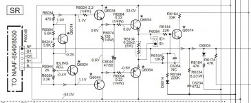
If you look at most Japanese receivers over the last 20 years, the "protection" circuits are generally simple. Attached is a simple amp used by a lot of companies. Q6074 senses output over-current and voltage. If an output device shorts or you short the amp output, you get a protection fault and the speaker output relay opens.
Unfortunately your schematic is the graphical equivalent of TLDR. What is the goal of this circuit?
If you look at most Japanese receivers over the last 20 years, the "protection" circuits are generally simple. Attached is a simple amp used by a lot of companies. Q6074 senses output over-current and voltage. If an output device shorts or you short the amp output, you get a protection fault and the speaker output relay opens.
Attachments
Last edited:
Can you supply a general explanation of the circuits as a starter, aka a block diagram with steep functional discriptions?This work was done a while back so I will have to remember how all the pieces fit together🙂
Potentiallyincorrect, this is a potentially incorrect reply!I prefer to use a condom.
Thanks Mark, Jan, Bonsai et al. Thanks you all for your kind words. Busaboy, yes protection varies in complexity from non existent, simple, medium to complex. Yes in the schematic you have attached instead of VI limiting they are doing something else with the detected over current. Keep it simple provides reliable results. Keep it simple as possible opens up your world. The simple version is below. Citizen124032 it provides overcurrent, over temperature, speaker delay and powerloss detection. Lee Knatta I sometimes cannot explain how pharmacists read doctors scribble 🙂, will try do a better job in time. Potentiallyincorrect 😉.

Not really the user's fault. EasyEDA is mostly a PCB tool, featuring parts apparently from LCSC, in huge slow-opening lists. Took me over 2 minutes to find "a 741" which was recognizably an opamp. (Would be faster next time now I know the sorting.)no built in symbol for a jellybean single opamp like the 741. Wow.

And a TO-99-8 !! Too cool for school!
I somewhat decoded your circuits - there are references to some power supply voltages (47, 12, 5, Vcc), but no circuits. The 47 is odd, Vcc undefined.
You're pushing a small current through the load to detect dc overvoltage. How about the response of the the controlling feedbackloop of the involved amplifier on this?
Still, a block diagram would clearify a lot of all incorporated electronics, components, configurations and what not.
The circuits are drawn by modular design in 2020-06-... Any links to OnAudio?
I will make a writeup soon. At the time I designed these I was impressed at the outcome then. Once I start the write up, I will probably be impressed at my work (self error checking can be biased) or I will change a few things 😉I somewhat decoded your circuits - there are references to some power supply voltages (47, 12, 5, Vcc), but no circuits. The 47 is odd, Vcc undefined.
You're pushing a small current through the load to detect dc overvoltage. How about the response of the the controlling feedbackloop of the involved amplifier on this?
Still, a block diagram would clearify a lot of all incorporated electronics, components, configurations and what not.
The circuits are drawn by modular design in 2020-06-... Any links to OnAudio?
the same thinking that created the problem can probably not solve it😎, we are limited by our ideas and thots
- Home
- Amplifiers
- Solid State
- Protection