Hey guys I was wondering if someone could draw up this crossover for me - much appreciated! I would like to do some mods to the crossover to tame the tweeter a bit.
Thanks in advance.


Thanks in advance.

Does this look right?
If that is correct could someone explain what the heck is going on here lol
Last edited by a moderator:

Was wondering if you could explain what they are doing with this as well? ThanksHope this may help.
a WAG - some sort of tank circuit formed by C4, C3, L2?, or perhaps C4 & L2 are an attempt to get a steeper HP slope, the odd earthing an attempt to modify the slope?
The series capacitor at the negative terminal isn't so unusual but when combined with the inductor to that terminal, it's 'creative'. It simulates fine and I'd recommend starting there.
If it were me, I'd probably develop a second circuit to do precisely the same filtering with a more 'open to tweaking' topology. I can give suggestions if you like, and have a simulator ready.
If it were me, I'd probably develop a second circuit to do precisely the same filtering with a more 'open to tweaking' topology. I can give suggestions if you like, and have a simulator ready.
Bit of a nightmare to untangle this Dynaudio Heritage Special, but I think we are just about there, thanks to AllenB and tuantran's work.
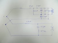
The bass section is 1.4mH series bafflestep and rolloff, and 4.7R and 4.7uF shunt which is just impedance correction really. Seems to be a 4 ohm woofer.
The tweeter section is some R1 resistor called a Mundorf MResist Supreme followed by a 3.9uF which is the first order rolloff.
This being a Dynaudio "First Order" crossover with the usual Esotec or Esotar tweeter, we now have a ladder or phase network of 2 coils and 2 capacitors. 0.5mH and 6.8uF values. Time delay really.
Zaph has done this sort of thing in the ZD5:
http://www.zaphaudio.com/ZD5.html
Finally, it looks like the tweeter is shunted with a R3 22R and a R2/C4 Zobel, which might be 6.8R and 1.5uF.
A couple of other similar Dynaudio circuits,


I have simulated these things, and they turn out a bit like the more regular Butterworth 3 with the tweeter polarity flipped.
I would guess increasing R1 will take the tweeter level down. I can't remember resistor colour codes, so maybe you can just measure R2.
The bass section is 1.4mH series bafflestep and rolloff, and 4.7R and 4.7uF shunt which is just impedance correction really. Seems to be a 4 ohm woofer.
The tweeter section is some R1 resistor called a Mundorf MResist Supreme followed by a 3.9uF which is the first order rolloff.
This being a Dynaudio "First Order" crossover with the usual Esotec or Esotar tweeter, we now have a ladder or phase network of 2 coils and 2 capacitors. 0.5mH and 6.8uF values. Time delay really.
Zaph has done this sort of thing in the ZD5:
http://www.zaphaudio.com/ZD5.html
Finally, it looks like the tweeter is shunted with a R3 22R and a R2/C4 Zobel, which might be 6.8R and 1.5uF.
A couple of other similar Dynaudio circuits,
I have simulated these things, and they turn out a bit like the more regular Butterworth 3 with the tweeter polarity flipped.
I would guess increasing R1 will take the tweeter level down. I can't remember resistor colour codes, so maybe you can just measure R2.
Ya please do - I love the box and the drivers but the setup of the cross over is “too special” for my tastes. Thank you kindly!The series capacitor at the negative terminal isn't so unusual but when combined with the inductor to that terminal, it's 'creative'. It simulates fine and I'd recommend starting there.
If it were me, I'd probably develop a second circuit to do precisely the same filtering with a more 'open to tweaking' topology. I can give suggestions if you like, and have a simulator ready.
Ya if you could sim it that would be fantastic. The tweeter alone with a MM is around 5.3 ohms. Not sure what you mean for the impedance plot sorry?Yes you'll sim it, or yes you'd like it simmed? Do you have an impedance plot for your tweeter?
Impedance plot shows the impedance vs frequency, because it varies. Otherwise I'll simply use a generic 8 ohm load.
Do you know the values of the inductors?
Do you know the values of the inductors?
Only what tuantran wrote down in his schematic. Not sure how he got those values tho?Impedance plot shows the impedance vs frequency, as it varies. Otherwise I'll simply use a generic 8 ohm load.
Do you know the values of the inductors?
Steve, you may have nailed it here. I missed it, but yes the two capacitors are the same and so are the two coils.we now have a ladder or phase network of 2 coils and 2 capacitors
So, the components highlighted in red are for phase manipulation (possibly delay compensation).
The components in blue are for upper impedance variation management.
In green are for setting the level and general impedance variation management.
The component in orange is the crossover 🙂
- Home
- Loudspeakers
- Multi-Way
- Crossover Help - Dyn Heritage Special