I have tried to understand my XO, and asked about it before. I first thought it was a Butterworth or an LR or adjusted to some measurements, since it didn't pass with the values that are in the filter. And I know that you cannot just calculate the exact value, as the impedance is not constant and other things. But since the tweeter is 8.2 µF capacitor and a 0.2 (0.22) mH coil, so it is actually very close to a 2. order Chebychev. If you just use a calculator, a LR generally gives a relatively small capacitor and a relatively large coil, a BUT gives a slightly larger capacitor and a slightly smaller coil and a Chebychev gives a large capacitor and small coil. Just like my HighPass. As I have read it, Chebychev has a Qualityfactor (Q) of 1, and BUT of 0.7 and LR of 0.5. According to The Crossover Design Cookbook by Mark Lawrence, a Q value of 1 is too large and it will sound terrible with a lot of ringing. There are probably many errors with my speakers, but ringing is not an issue, it's a rather polished sound mayby to polished.
What I have read should beeing the advantage of Chebychev should be that it rolls off faster. Then I get confused again. Rolls off faster, that's a 2. order filter, so all the filters probably roll off equally fast, i.e. 12 dB per octave ore have I misunderstod. Ore does it means that the rooloff is more "sharp" when it starts to roll off.
By the way, it also surprises me that by playing a little with different XO frequencies in a calculator and an impedance of 6 ohms, the XO frequence is just over 3,000 Hz. The Bass is cross by a 2.2 mH coil, and then a coil a resistor and a capacitor in parallel with the Bass. So the low-pass filter is probably just a 1st order filter with an LRC filter. 1st order filter with a 2.2 mH coil gives a XO approx. 500 Hz. That gives now sence.
The way impedance variations typically affect a filter is near the 'knee'. The passband and rolloff slope usually stay near the same.
If your filter does produce a small peak at the knee, and there is a dip in the response then they will balance out.
If your filter does produce a small peak at the knee, and there is a dip in the response then they will balance out.

The Knee, is it the 3 dB og so peak at the XO ore what is the Knee (I am danish so dot familiar wit that).
Is it the knee or +3dB bump that Mark Lawrance refers to as "ringing". Does this mean that if the tweeter has a characteristic so that the sum gives a linear frequency curve, then it is OK with a Q of 1.
I still wonder about the that the bass is cut at 500Hz and the tweeter at 3000 (if you just calculate from a calculator) and I think that the drivers can't be so different from idial that it will be connected. Or how should my bass filter be understood
Sorry for asking so much, I just want to understand.
Yes, it's OK to use a higher Q filter if it combines with a lower Q response. I have no problem using a filter with a Q higher than 1 if it's for the right reasons.
I guess we could do a bit of simulation with some dummy drivers and try to get a clue what the filters are doing... I'll see what I can do.
I guess we could do a bit of simulation with some dummy drivers and try to get a clue what the filters are doing... I'll see what I can do.
Ok this helps. First, notice that I've lifted the woofer by 6dB for the baffle step.
The woofer seems to have a shallow fall for the baffle (it may come back to flat in reality). The RLC then kicks in and provides a steeper rolloff near the cross.

The woofer seems to have a shallow fall for the baffle (it may come back to flat in reality). The RLC then kicks in and provides a steeper rolloff near the cross.
Now a little understanding is beginning to come to me. And the Baffel step that you write is of utmost interest to me, as my cabinet is largely without a baffle, it is a cylinder without a flat front, but where the bass and tweeter sit inside the round. That was one of the next things I had to ask about. If we assume that there is no aextra input from the baffle (baffle step), then the frequency respons should probably bee so that the speaker was on the very bright side. I don't think it is either. I guess I'll have to look into getting some measuring equipment.
Thanks. I will poste af picture off my speaker so you can se the baffel
Thanks. I will poste af picture off my speaker so you can se the baffel
This is what my newly built speaker looks like. As you can hopefully see, my strong side is more on the carpenter side than on the XO. And I am well aware that such a cabinet will not be to everyone's taste. The stand is af part off the speaker as the reflex comes out there.
Attachments
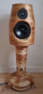
I like it. Also if you want to use a cylinder, that's the best direction to use it.
The simulation shows the baffle step compensation near 800Hz. I think this appears close to what it should be. A box with a flat front can have a slightly lower frequency but the cylinder gives a smoother transition.
The simulation shows the baffle step compensation near 800Hz. I think this appears close to what it should be. A box with a flat front can have a slightly lower frequency but the cylinder gives a smoother transition.
That the shape should have a smooth response is also one of the ideas for my design. But the shape is aæso a function of the manufacturing method. 1½ years ago I got the idea to make a full speaker that was turned on a lathe. I've never seen it like that before. Something has obviously been made where the cylinder lies down or round sphers, the methods I use are much, much more difficult as the holes have to be turned into the wood where it is most difficult.
I like it. Also if you want to use a cylinder, that's the best direction to use it.
Sort of. It's not easy to put a driver in the side of a cylinder like this. And also the idea that a circular baffle is ALWAYS bad is not correct. It turns out that the effects of the enclosure shape, as investigated by Olson and others, often fails to convey one very important point: the relative diameter of the source (the loudspeaker cone) to the baffle (the edge of the surface surrounding the cone) has a strong influence on the magnitude of the diffraction effects/ripples above the transition region.
Olson, in order to more clearly show the effect of different shapes, implemented a setup that was very close to a point source. That is to say he used a driver with a very small diameter (IIRC 0.75 inch diameter special fullranger) and much larger cabinet diameter (all objects in his paper were 24" across). This gives the maximum effect, which was useful for his purposes since that is exactly what he wanted to show. But this has had the effect of making people think that some enclosure shapes are really, really bad. It's not always the case.
It turns out as the driver cone diameter approaches the diameter of the baffle, the diffraction ripples mostly go away and you get a response shape that is similar to what you get that for a sphere - a very smooth transition both on and off axis. Recent simulation work by Mellow and Karkkanien (sp?) has demonstrated this effect nicely. Even for the case of a driver in the end of a cylinder, which creates a circular baffle around the driver, as long as the driver is close to the size of the circular baffle, the response is very smooth.
This is one effect that I have taken an interest in, because I use drivers "nude" in my dipole loudspeaker systems. The driver mounting frame is essentially a round baffle surrounding the cone. But the diffraction signature is smooth or absent (depending on how you look at the phenomenon). Someone once asked me "isn't the diffraction really bad because of the circular frame edge?" and I had to think about it and look at my measurements to convince myself that the mantras we have learned from Olson and others omits the rather important cone-to-baffle ratio effect.
I'm actually thinking of also trying to make a cabinet where the cylinder lies down. I agree that if there is a baffle, there will be the same distance to all sides so that there is maximum reflection. If I were to make it horizontal, it would be with a minimal baffle that was only as big as the unit and then round it off. If you needed a larger volume, the cylinder had to be bigger at the back, just like a barrel. In that case, I think the reflection must be minimal. As I said, it is much, much easier to turn like this, as it is the right way to turn into the tree. There is a Korean company that has such lying cylinders
That is amazing. If I thought of turning the tweeter cutout with the taper there, I would have done it by hand instead. Very impressive 
@CharlieLaub if a person takes it all the way like I've seen you working on, I think it's interesting what can be done.
However what a lot of people say is that they'll try to reduce the baffle a bit in size, and they see a certain consistency appearing in the polars and think it's an improvement, but I disagree that this geometric effect gives the full story.
It may tend to downplay very early HOMs. These are also at a tight listening angle to the direct source and are difficult for the brain to separate. They may be considerable. The saving grace may end up being the precedence effect.
Thanks Allan. When I got the idea I thought why hasn't anyone had this idea before. But when I first started the project I found out why. As I said, it is quite difficult almost in an idiotic way. But at the same time it is also quite unique. It is actually my idea to make such cabinets for people with DIY projects. It would then have to be done based on the kit I have or other kits. In Denmark, where I live, however, no one has signed up as buyers. This is just an idea for how it could look, it was also one of my ideas that the customer helped decide. The only requirement was that it had to be turned or a big part of it must be turned as it is just like that which is my idea.
@AllenB
You mentioned HOM: I translate as "higher order modes". I don't quite understand why you are mentioning that. I typically associate them with horns or other resonant cavities. Can you explain what you mean regarding cabinet diffraction, or were you relating those to some other aspect of the conversation here??? Sorry I am a little confused!
You mentioned HOM: I translate as "higher order modes". I don't quite understand why you are mentioning that. I typically associate them with horns or other resonant cavities. Can you explain what you mean regarding cabinet diffraction, or were you relating those to some other aspect of the conversation here??? Sorry I am a little confused!
Hi AllenB,
could you please amplify the statement above?
Kindest regards,
M
However what a lot of people say is that they'll try to reduce the baffle a bit in size, and they see a certain consistency appearing in the polars and think it's an improvement, but I disagree that this geometric effect gives the full story.
could you please amplify the statement above?
Kindest regards,
M
Substitute the term with diffraction modes.I don't quite understand why you are mentioning that.
For example, regular narrow cabinet baffles.. or did I not understand you?could you please amplify the statement above?
- Home
- Loudspeakers
- Multi-Way
- 2. order Chebychev 3000 HZ and 1. order 500 Hz - Why?