Hi!
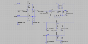
I would like to try connect the amp like at attached picture, I need you advice which chip has the chance to work without oscillation with the gain set 10 times or higher, it should have diff input.
The reason for this is curiosity, compactness, simplicity, efficiency and possibly gorgeous sound (like in other AB class transconductance amps, for example the link:https://www.diyaudio.com/community/threads/lm1875-transconductance-amp.270956/ ).
thank you in advance for any suggestions!
Attachments
OK, the question was not easy,
what D class chip with good stability and differential input would you recommend in general?
thank you in advance!
what D class chip with good stability and differential input would you recommend in general?
thank you in advance!
TDA8932 sounds gorgeous when fed with clean power (both power terminals, but most especially pin8)
The datasheet for the TDA8932 recommends capacitively coupled inputs even with a symmetrical supply. You'll have to be careful to avoid instability at high frequencies.
I tried some simple experiments a while ago with that chip but I could only get 20 ohm output impedance @ 20 khz until it started oscillating like crazy: https://www.diyaudio.com/community/threads/any-current-mode-class-d-ics.379267/
I just used an existing board though and kept the input caps. I'm considering toying some more and bypassing the input caps with an quadfillar transformer such that one primary winding is the input, the other primary winding is across the current sense. The secondaries are the inputs for the chip.
If you do succeed getting decent output impedance with that or another chip it would be awesome.
I took a look at the schematics in your linked thread - did you only try running TDA8932 in BTL mode? I wonder whether the carrier presence might contribute to instability and you need really excellent CMRR for the sense amp when running BTL. Something like AD830 has impressive CMRR at HF I recall. But perhaps SE mode would be simpler?
Yup, only tried BTL where the voltage across the sense resistor -> input was achieved with a transformer or an opamp.I took a look at the schematics in your linked thread - did you only try running TDA8932 in BTL mode? I wonder whether the carrier presence might contribute to instability and you need really excellent CMRR for the sense amp when running BTL. Something like AD830 has impressive CMRR at HF I recall. But perhaps SE mode would be simpler?
Possible that SE would be more simple but would probably require symmetrical supply since output caps cause problems. I don't have access to a SE board so I went with BTL when I tried.
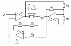
Nope, I fed the feedbacked input signal into both sides which might have contributed to the instability problems.Did you try this topology?
My goal was to see if I could pick a cheap off the shelf TDA8932 board and just add some current feedback and see if it works without having to change the boards. And no, it didn't. Might work though if you adjust and do for example this circuit. And might help if you make the feedback input bypass the input caps to get it DC coupled.
I did succeed in getting ~ 100 ohm output impedance if I remember correctly with a DC coupled Hypex NCore single bridge amp. It doesn't have as much gain though so I had to add gain and i only got a transformer frontend to work without stability problems. Opamp would probably be better but I'm not experienced enough with them to work without problems. I ususally build Class A cap coupled circuits with little to no feedback and this is a bit different.
Thank you OllBoll,
it looks like I had the same idea: to buy ready 8932 amp (in the price of a single chip) and modify it to transconductance mode.
The 2 pcbs which I bought (didn't arrive yet) are 35W mono amp, this means they are working in bridge mode, so I will need to buy NE5534s and use them like in post 10. I need additional +-15V ps.
It is a bit unclear for me how to modify the circuit with soldered 8932, it looks like gnfb net is hiden in the chip?
Hi Abraxalito,TDA8932 sounds gorgeous when fed with clean power (both power terminals, but most especially pin8)
I will use traditional transformer/bridge/caps power supply.
thank you for suggesting pin 8 to powering. Is other pin designed to be powered too?
In my TDA8932 amp I use a regulator (LM317) to power pin8 separately from the main power pins (pins 20 & 29). You will need a diode between those two rails if you go that route as pin8 must never be allowed to be more positive than the main supply. More negative is OK though, it limits the max output swing.
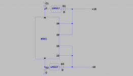
Not quite - the diode isn't to go in series with the reg. Its wired between pin 8 (anode) and pin 20 (cathode). I've not tried the chip with symmetrical +/- supplies so can't comment on whether pin 9 needs the same treatment.
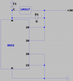
The diode's right now. Its worth bearing in mind that because of the LM317 dropping the +30V main rail voltage you won't get the usual ~99% of the (pin 20) supply output swing. The pin 8 supply voltage determines the maximum output level, not the pin 20 supply.
Probably I will use simply capacitance multiplier or Zener + NPN stabilizer instead of 317.
So is it possible to power pin 8 with max 36VDC and pins 20,26 with higher, for example 45VDC?
So is it possible to power pin 8 with max 36VDC and pins 20,26 with higher, for example 45VDC?
- Home
- Amplifiers
- Class D
- is there class D chip which could work in transconductance mode?, please advice