Wow! I have seen a lot of recycled caps before (been inside a lot of Lepai 2020s) and those take the cake. The negative stripe on the one of those looks completely beaten or lazily faked. Even if they claimed to be NOS, the O deserves emphasis. Or just poorly stored. Or stored in an iron foundry. That's nasty.Not verified but misprinted sleeves. I don’t trust them. They are already in the bin. Ah got them out for you.
Even if they would be original.. they’re different series and look used or recycled. Datecodes also all different.
The A8 is cute. Aiyima's marketing never fails to make me smile. Does the switching pot make any pop on start?


Zek, solid bass is one of the strongpoints of the A8. Please mind this is a sub 100 Euro device so all is relative. Bass is better than the unmodified BRZHiFi. It can perform quite well but it needs some work. I will see how far I can mod it. For science 😉
MKHunt, it makes no noise at all but with 5 opamps there was mechanical coil whine when switching it on. That is gone after removal of all the line out stuff including all resistors and decoupling caps. So it seems it was because of the starting 12V switcher but I’ll look closer to it.
Solve, A8 IS a Merus device.
* again it becomes clear that ceramic caps of sub X7R quality are a bad choice for coupling. Even a 100 nF film cap in parallel improved sound quality. Not a fan of paralleled caps but there is not much other choice. The curse of MA12070 is that it needs many caps around it.
Last edited:
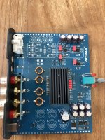
Like this (not finished). C38 and C39 are now 0 Ohm 0805 to bypass the bass boost nonsense. The switch itself is also gone.
* please note the 78M05 used for the 5V. No switcher here, only a 12V switcher feeding the 78M05 12V at its input. Good, it may be the reason of its acceptable performance.
* please note the 78M05 used for the 5V. No switcher here, only a 12V switcher feeding the 78M05 12V at its input. Good, it may be the reason of its acceptable performance.
Attachments
Last edited:
It has some really nice curiosity friendly parts! Tle labeled pads on the inside for the outputs is nice. Single row output might support the 2-pin bananas?
And the ground pads on the edges are good effort. Anodizing is an insulator though (aluminum oxide). Maybe they scuffed the inside rails of the case so it can make contact?
Your desoldering is so clean. I'm also starting to believe you may have a stockpile of small wima caps on hand at all times. Great to hear about the lack of pop.
Is that a microcontroller in the lower right corner next to the 78M? I'm super curious what it is. 8-pin? 8-bit? ATTiny? Maybe the pot switch energizes the MCU which then performs a soft start/unmute?

ETA: Also curious what the bass boost circuit does. It looks like the switches might have been under that top opamp which remains? There are four PTH that seem to be about where photos show the switches. Have you figured out what Aiyima is doing there?
And the ground pads on the edges are good effort. Anodizing is an insulator though (aluminum oxide). Maybe they scuffed the inside rails of the case so it can make contact?
Your desoldering is so clean. I'm also starting to believe you may have a stockpile of small wima caps on hand at all times. Great to hear about the lack of pop.
Is that a microcontroller in the lower right corner next to the 78M? I'm super curious what it is. 8-pin? 8-bit? ATTiny? Maybe the pot switch energizes the MCU which then performs a soft start/unmute?
ETA: Also curious what the bass boost circuit does. It looks like the switches might have been under that top opamp which remains? There are four PTH that seem to be about where photos show the switches. Have you figured out what Aiyima is doing there?
Last edited:
What a nice information anmd explanation. Thanks.View attachment 1094632
It's just saying you can have a 1.8Vpp input somewhere in the voltage range where the peaks and torughs do not exceed a certain positive or negative voltage above/below amplifier virtual ground. (-0.5 to +6V) before shutoff.
The line item above the audio signal level just means that the amp can 'deal with' an offset up to 3.8 V in the positive direction (4.8V Peaks with 3V troughs). Note that these are after the input capacitors. Specs are for the bare chip.
Examples:
All of these waveforms are okay because they do not exceed 1.8Vpp and they do not go above 6V and below -0.5V. If you exceed 1.8Vpp the chip will try to adjust the waveform offset which may distort or oscillate, even if it is in the acceptable range.
View attachment 1094660
View attachment 1094640
Gain staging with the MA12070 will give you the best results because even consumer gear can overdrive this chip. Note that consumer 0dBV reference is still 2.828Vpp and 0dBu level is still 2.19Vpp. My Marantz NR1711 will output ~5.4Vpp from the pre-outs before clipping. My STR-DN1060 will output ~4.6Vpp from Zone2 before clipping. My friend's STR-DN1070 will output the same. A to-spec CD player can easily output 2Vpp. Usually they go a touch higher to around 2x higher (4Vpp from a CD player is not uncommon). A decent phono preamp can go as high as 1.2Vpp depending on cartridge and gain. A cheap phono preamp can go higher.
View attachment 1094655
At max, the MA12070 can take about -5dbV input. This might be a little annoying for people at first, but the closer you can get to the Vpp max of the MA12070, the greater the signal:noise ratio. You can always use a cheap RMS multimeter to measure between the center and surround on an RCA output then convert RMS to Vpp and set a volume limit.
This is safer and easier than trying to measure the amp outputs or volume pot pads to mark the volume potentiometer since most of these lower-cost amps have pretty poor pots, and the ground of your meter is likely very different than the amp ground (leading to potential speaker damage.... ask me how I know).
Here is a nice writeup on gain staging and noise floor for maximum dynamic range with systems using different levels. It is focused on mixing +4dBu and -10dBV systems, but since consumer gear follows standards very very loosely I believe it can help a lot of people.
https://www.hometheatershack.com/th...rom-pro-audio-equipment-in-your-system.35677/
The MA12070 is a good chip. But you have to play by its rules. Having a larger AC waveform (VPP) won't kill the chip (within limits) but exceeding the DC offset will let the magic smoke out.
There is no volume control in my amplifier. So i want to put a protection circuit in front of inputs right after input caps.
Can you please suggest me a proper one.
Attachments
Yes I have the 2.5 mm and 5 mm by Wima in numbers. Not a hoarder (note to self: stockers are not hoarders) but the experience with good stuff is that it is often declared obsolete because of low demand as cheap is king. And good industrial quality through hole parts are over before you know it. The 2.5 mm 1 uF is excellent but I am out of those and they’re harder to find.It has some really nice curiosity friendly parts! Tle labeled pads on the inside for the outputs is nice. Single row output might support the 2-pin bananas?
And the ground pads on the edges are good effort. Anodizing is an insulator though (aluminum oxide). Maybe they scuffed the inside rails of the case so it can make contact?
Your desoldering is so clean. I'm also starting to believe you may have a stockpile of small wima caps on hand at all times. Great to hear about the lack of pop.
Is that a microcontroller in the lower right corner next to the 78M? I'm super curious what it is. 8-pin? 8-bit? ATTiny? Maybe the pot switch energizes the MCU which then performs a soft start/unmute?
View attachment 1094973
ETA: Also curious what the bass boost circuit does. It looks like the switches might have been under that top opamp which remains? There are four PTH that seem to be about where photos show the switches. Have you figured out what Aiyima is doing there?
I think the 8 pin SOIC is the 12V switcher. RC filtering is done with the 470/16 and SMD caps.
The GND pads are nice but grounding is mainly done with a thin wire going to the quite good potentiometers axle/threaded bushing.
Under the heatsink some choices can be made with solder blobs.
The bass boost was done with a cap. It was shorted with a dip switch accessible through an opening in the bottom. As it is good with bass the bass boost was unnecessary. Just like the high part count line out circuit. If they would have omitted all that stuff they could have used better caps 🙂
It sounds nice now.
BTW what are 2 pin banana plugs?!
Last edited:
I recently learned about them, and it felt like my prior life was full of so much worrying about loose plugs vibrating out just enough to short and blow.
They are a magical beast that seems to work with most non-Chinese amplifiers.

Positive and negative with fixed spacing and no way to short out. Some sort of convenient magic. On the mini Chi-fi amps with vertical +/- separation they tend not to fit, but maybe with a horizontal spacing? ETA: .5"/12.7mm center-co-center spacing.
I should have bought a bunch of the wimas when an 'expensive' cap was 75 cents. You were wise. I think Mouser and Digikey want over $3USD per box cap for 4.7/6.8uFs now.
AH! The thin bare wire is the pot ground! I was curious what that was.
The more and more I take the PA3s' boards out of the housings, the more I get access to 'bonus' ground points where the extrusion touches the board. I still maintain that they are good pieces of kit, but they were clearly never designed to be disassembled and the internal resiliency (or lack thereof) shows.
The solder mask on these boards is just... I have stains on clothing and aluminum with far more tenacity.
I've only been inside the Aiyima Tube T6 Pro, but that mask was thick like paint. Perhaps the A8 is similarly robust? Shunt modding Nvidia graphics cards was also easier than working with the topping pb-free solder. Good amp; awful construction.
They are a magical beast that seems to work with most non-Chinese amplifiers.
Positive and negative with fixed spacing and no way to short out. Some sort of convenient magic. On the mini Chi-fi amps with vertical +/- separation they tend not to fit, but maybe with a horizontal spacing? ETA: .5"/12.7mm center-co-center spacing.
I should have bought a bunch of the wimas when an 'expensive' cap was 75 cents. You were wise. I think Mouser and Digikey want over $3USD per box cap for 4.7/6.8uFs now.
AH! The thin bare wire is the pot ground! I was curious what that was.
The more and more I take the PA3s' boards out of the housings, the more I get access to 'bonus' ground points where the extrusion touches the board. I still maintain that they are good pieces of kit, but they were clearly never designed to be disassembled and the internal resiliency (or lack thereof) shows.
The solder mask on these boards is just... I have stains on clothing and aluminum with far more tenacity.
I've only been inside the Aiyima Tube T6 Pro, but that mask was thick like paint. Perhaps the A8 is similarly robust? Shunt modding Nvidia graphics cards was also easier than working with the topping pb-free solder. Good amp; awful construction.
Pfff is that not a little exaggerated? Just like the Brits that thought they would be electrocuted by normal banana plugs and use those annoying BFA 🙂 My WBT bananas don't fit on Chi-Fi amplifiers. Therefor I used simple banana plugs and this time with metal cover. I had to rethink that when the Sabaj A10a died and I plugged out the speaker plugs in a hurry and had both the + plugs touching chassis.....BTW there is a detail worth to mention: those banana plugs with separated spring cylinder often make insufficient contact. The older silver (later nickel) plated Hirschmann multi spring banana plugs are way better. Well almost anything German produced is to be preferred over todays Chinese alternatives as almost anything breaks down prematurely. They do have that nice gold shine though. Switches idem ditto. I would pick even the plain Jane Marquardt 1835.3105 mains switch over the stainless steel ring-LED China types without any doubt. Opened a few and they had steel contacts but oh boy what a nice blue LED. One was measuring 38 Ohm!
Wima is one of the old fashioned quality brands and it is local produce so I only use Wima. Although I of course see the lack of many simple parts I did not realize what you are telling is right: by chance I bought Wima by the tens and hundreds. As I mentioned being out of the excellent 1 µF 2.5 mm MKS I checked yesterday where to find them and noticed them being 1.68 Euro a piece! Earlier this year I bought a bag filled with 50 of those 2.5 mm 100 nF caps and paid 10 Euro shipping included....Those days are over.
Can you explain breakthecap that overvoltage protection is not a solution for any other unexpected issue that may occur when a "open" amplifier is used? Many hardcore DIYers made the same mistake (hardware volume control = 666) and some paid with burned woofers. Some even more than once and for some reason more often so with the types that leave stuff running unattended 24/7. Not to mention that overvoltage protection with non linear parts may have a detrimental effect on sound quality. Throwing away the baby with the bath water is it called here.
Last edited:
Apologies mate, I missed this one/What a nice information anmd explanation. Thanks.
There is no volume control in my amplifier. So i want to put a protection circuit in front of inputs right after input caps.
Can you please suggest me a proper one.
I may not have been very clear before. I do not think an overvoltage circuit is needed at all. I was just trying to say that one needs to measure their max output before the amp and then tame it.
In proper gain staging, you want the signal to be as strong as it can (without clipping/distorting) at the beginning of the chain. Every time you add gain or adjust gain at different stages, you might introduce noise or some data loss (in the digital domain, if your volume is not done in the 32-bit or higher domain)
The need for measurement (Usually at 1k or 2k sine wave 0dbFS) is so you can make sure the maximum output is still a bit below the amplifier's maximum input.
We like to say 'ground' for many things, but in any IEC Class 2 device, Ground is usually a virtual ground which may be a few mV above true ground, or it may be up to 10-15V above true ground.
If we go back to college Physics 2 courses and think of electricity in terms of water, the voltage is pressure and the current is flow. Now imagine each of your devices has its own working voltage (pressure) and it is a little like a holding tank for fluid. The air above that fluid is your ground potential. If the entire holding tank is 1mBAR or 2PSI above atmospheric, it doesn't matter to the contents of the tank because in reference to each other (IEC CLass 2!) they will only see a pumping (Voltage) difference. However, if you add more 'loops' (other devices) of other fluid into that system, you may have tanks with different total pressures (ground potential) which will then try to equalize through your ground {air return} connections to the lowest pressure device (true earth ground). So you may see +-1.5V at your DAC charge pumps, but if the DAC is wired to IEC Class 2, its earth voltage may be +5V (virtual ground) so your actual out-of-system charge pump might be flowing a wave that spans 3.5V to 6.5V.
This same trickery is why gain staging is soooooooo important. Maybe your noise floor is at an actual 2VDC offset, so to deliver quieter performance your AVR or DAC sets the offset to +5VDC so the signal does not clip into the noise floor. This is part of gain staging. But a capacitive charge pump works in the DC domain by feeding DC current to 'lift' the waveform to a higher nominal potential. So if you just go direct into the MA12070 chip, you are feeding a lot of DC current and it will go pop. Input coupling caps serve the purpose of filtering the DC out of the AC waveform but capacitors also attenuate high frequencies because they kiiinda look like DC. Here's a nice (not accurate) meme to illustrate:
Now, how do we deal with all these different sizes of audio waveforms and how can we avoid having all our equipment avoid hissing, warbling, making weird garbage noises?
Gain staging!
If we send full strength signals all to our final volume control device, then it will either be shrunk in the digital domain (bit shifting peaks and toughs closer to -Ve) or in the analog domain (via resistive voltage/impedance dividers). The amplifier can still keep its capacitors which will prevent it from going pop bang and letting out the magic blue smoke, but we have full control of our sine wave amplitude (volume) by changing the apparent impedance/resistance of the destination (your amplifier).
The easiest way to gain stage, if to measure, record, and map. Here is a map of my (Home theater/physically large entertainment) system. I have many others, but this is the most complex because it includes the most 'legacy' equipment.
The Driverack PA2 is awfully noisy when it is in the consumer (-10dBV) gain mode. So I must use +4dbU which is a much larger waveform (more voltage peak to peak). BUT! My poor MA12070 amplifiers will hate that load. So the last point where I can keep my maximum signal strength is the driverack. If I cut its gain in half, it sounds awful because it uses a 24-bit 48kHz codec. SO what to do? How to keep the amplifiers safe, avoid ground problems, but still provide a ground reference (at the amplifiers) that they can use to compare the signal (this is what keeps DC offset low)?
Attenuate! Passive attenuators. Also known as a volume control. For a balanced connection it is a U-Pad and for a single-ended connection it is an L-Pad. In my diagrams I have attached a -13dB resistive U-Pad (matched to the 9.6k input impedance of the MA12070 and the 120-Ohm output impedance of the driverack). It is basically a signal-level non-adjustable volume knob. 1.5Vpp in (-10dbV)? .7Vpp out! 4Vpp in (+4dBu)? 1.7Vpp out!
But then, one may ask, IF
then why do people say analog volume potentiometers are bad? In short, this is because we are all very cheap. A very good volume control is not very affordable. And a very affordable volume control is really quite terrible. We could talk about how potentiometers are built, but the long and short of it all is that there is usually an imbalance between the different channels of a volume potentiometer. In order to make sure that your 2-4 channel volume potentiometer has the exact same value on all 2-4 channels at the exact same positions is either expensive to manufacture or it becomes quite large.
So in short:
- Digital volume control is 100% great as long as it is handled in 32-bit or higher digital domain. Even after attenuating, you will still get 24-bits of data and cover the entire sub and super-harmonic frequency range.
- Please do not remove the input caps.
- Measure your sources, try to get gain as early in your chain as possible (where you can get sufficient levels without distortion).
- If your final output before the amplifiers has too much gain (and you only want to use them as power amps to avoid volume headaches) then add a passive attenuator to the output of that source or the input of your amplifier (when adjustable, sometimes this is called a volume potentiometer XD ). There are many sites to help with this, but you must know the impedances from manuals or tech documents.
- Enjoy the music.
- No special circuit is needed. Just maybe don;t try to pump out a ton of DC on the outputs.
- If the potentiometer is in the feedback loop of the amplifier, then it is not a passive attenuator for the input signal, but instead an adjustable gain.
Last edited:
Of course! Short explanations are my specialty!Thanks for the short explanation 😀
okay. The DAC was outputting 2VPP which was not enough to to through the driverack and attenuators.
So..... slightly off topic but.... Soldering 1005 (sized) components by hand with terrible (learned that in process) tweezers and a T12-K tip was....... Let's just say it is not high on my recommendation list.
But it is done. My eyeballs need a rest. Yes they are crooked, no I am not a machine.
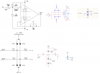
Modified I/V stage to match sims and nearly match schematics for 9038Q2M I/V stage (I used 1k instead of 820-Ohm). Only middle two resistors are shown.

Yes I touched the cap wrappers and no that's not damage to the crystal. It wiped right off.
More than that, it works. Here are stats and an o-scope reading of windows playing a 1 kHz tone into the DAC. Each photo corresponds to pin 2 or pin 3 of each XLR output.
Just a heads-up, cheap probes. But now I know the MA12070 will get a cleeeeeeeeeeeeeeeeeean signal well above noise floor of the driverack (can take up to +20dBu (21.9Vpp)


So..... slightly off topic but.... Soldering 1005 (sized) components by hand with terrible (learned that in process) tweezers and a T12-K tip was....... Let's just say it is not high on my recommendation list.
But it is done. My eyeballs need a rest. Yes they are crooked, no I am not a machine.
Modified I/V stage to match sims and nearly match schematics for 9038Q2M I/V stage (I used 1k instead of 820-Ohm). Only middle two resistors are shown.
Yes I touched the cap wrappers and no that's not damage to the crystal. It wiped right off.
More than that, it works. Here are stats and an o-scope reading of windows playing a 1 kHz tone into the DAC. Each photo corresponds to pin 2 or pin 3 of each XLR output.
Just a heads-up, cheap probes. But now I know the MA12070 will get a cleeeeeeeeeeeeeeeeeean signal well above noise floor of the driverack (can take up to +20dBu (21.9Vpp)
Keep on going. There is still to much black on the board. I see the board only as a device that holds the MA12070 chip and attach my four favorit coupling caps at the nearest soldering points to the chip. Same goes for the Outputs. Use the most beefy coils that fit on the board. I got rid of the constraining chassis and will use something bigger when all the tests are done.Like this (not finished). C38 and C39 are now 0 Ohm 0805 to bypass the bass boost nonsense. The switch itself is also gone.
* please note the 78M05 used for the 5V. No switcher here, only a 12V switcher feeding the 78M05 12V at its input. Good, it may be the reason of its acceptable performance There is still to much black
If done that way all the different MA12070 offerings sound best/identical.
Next on my list is a differential 3stepp volume control with matched resistors to adjust max wanted volume and protect my gear and ears.
That approach makes the most sense, with a system as mine:
Windows 2016 Server fully loaded into ram.
Monism diy Dante 4 way modules.
AKM AK4495 and AK4490 Dacs each differentialy coupled via 4 caps. No opamps on Dac or MA12070 Bord.
Equalizer APO enables me to have DRC and active Crossover on Movies and Music as well.
In minutes I can switch between my horn system, fullrangers, and other speakers.
For my Seos 12" tops I will use silver mica coupling caps on the MA12070 that roll off at 1khz as an additional protection.
Cheers Klaus
Hello, friends. Is it possible to replace the ferrite bead in the output filter with Murata BLM31SN500SN1L instead of the recommended BLE32PN300SN1L?
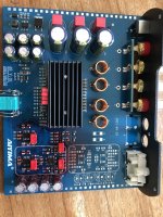
Since I was away I had to keep up so I went on. Just like Klaus I see the board as a device that holds the MA12070 but I don’t hate opamps as much 🙂 I planned the fake 6 x 1000 uF caps to be replaced for 6 x 470 uF 50V. Misjudgement happens so the 6 x 470 uF 50V panasonic FC for PVDD fitted but the board did not fit in the casing anymore. The caps are too tall.
So I corrected my mistake with another mistake. However it works.
3 x 470 uF 50V Panasonic FC in parallel with 3 x Wima MKS 4.7 uF 50V. Bass is very good and the stereo image is deep. Nothing measured (yet), I was not in the mood to even bother. The 6 x 470 uF 16V for the 12 and 5V are also replaced for Panasonic FC 470/16.
Attachments
Last edited:
Sure, it is possible. They are narrower and slightly taller, so the pad size should still allow attachment. Are your originals broken? or perhaps are you doing a design from scratch?Hello, friends. Is it possible to replace the ferrite bead in the output filter with Murata BLM31SN500SN1L instead of the recommended BLE32PN300SN1L?
I'm not sure if it;s that much of a mistake. Unless Aiyima is using a 2.5A or smaller supply the caps should never really be discharging much if at all I would think on a single chip. If this song doesn't break it up with all the deeeeeep and wide bass then your total capacity is totally fine. But in my experience the bass is mixed so wide it sounds like it's coming from almost 2x the speaker width. That should test the amp's power reserves nicely 😛 It feels like it goes down to maybe 20Hz or slightly lower. It;s got that strange bass feeling of just being enveloped in a muffled blanket instead of directivity to the punchSince I was away I had to keep up so I went on. Just like Klaus I see the board as a device that holds the MA12070 but I don’t hate opamps as much 🙂 I planned the fake 6 x 1000 uF caps to be replaced for 6 x 470 uF 50V. Misjudgement happens so the 6 x 470 uF 50V panasonic FC for PVDD fitted but the board did not fit in the casing anymore. The caps are too tall.
So I corrected my mistake with another mistake. However it works.
3 x 470 uF 50V Panasonic FC in parallel with 3 x Wima MKS 4.7 uF 50V. Bass is very good and the stereo image is deep. Nothing measured (yet), I was not in the mood to even bother. The 6 x 470 uF 16V for the 12 and 5V are also replaced for Panasonic FC 470/16.
Ah, I looked at it in Audacity, Yeah, this is a good test. SO much 20-80Hz.
The UCC KZN series 470 uF 16V seem to be original (but you never know for sure) and they have better specifications compared to Panasonic FC. So maybe the KZN should have stayed.
The 6 x 1000 uF 35V seemed fake. Bass is better than before with only 1500 uF Pana FC. Apparently it is enough. I really should have measured those 1000 uF caps.
The Sabaj A10a had 2 x 3300 uF.
The 6 x 1000 uF 35V seemed fake. Bass is better than before with only 1500 uF Pana FC. Apparently it is enough. I really should have measured those 1000 uF caps.
The Sabaj A10a had 2 x 3300 uF.
Last edited:
- Home
- Amplifiers
- Class D
- Infineon MA12070 Class D