Hello Everyone,
Which Output Transistors are best for Jean Hiraga Super Class A 30 W
for The real Quality of The Amplifier ?
Thanks in Advance..) 🙂
Which Output Transistors are best for Jean Hiraga Super Class A 30 W
for The real Quality of The Amplifier ?
Thanks in Advance..) 🙂

Nice You try to use other also ?I use sanken 2SC3284/2SA1303, hFE rank Y
Yes , 2SC5200/2SA1943 but 2SC3284/2SA1303 are betterNice You try to use other also ?
Hi all hiraga mamber
please help to correct the value of the schematic resistor and transformer that I use 18-0-18 after rectified at 25v.
Or can i use my schema and value with this component?…
is there any other good scenario for the component i have ? …
SK170-J47
2SA1015-2SC1815
BC550B-BC560B
2SC5200-2SA1943
Best regards
Rubah Ganteng
Attachments
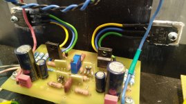
Finaly finisdh with this schenario below
input SK170-J47 -BL
casecode 2SA992-2SC1815
draver 2SA992-2SC1815
Transistor driver 2SC5200-2SA1943
R bias vr 1K pararel with 3.3K measure a cross R bias = 1.45v , measure R 1Ohm =0.70-0.8v
best regards
RG
input SK170-J47 -BL
casecode 2SA992-2SC1815
draver 2SA992-2SC1815
Transistor driver 2SC5200-2SA1943
R bias vr 1K pararel with 3.3K measure a cross R bias = 1.45v , measure R 1Ohm =0.70-0.8v
best regards
RG
It is not a good idea to use BC550B-BC560B as driver transistors; use medium power transistors as KSA1381 and KSC3503 instead.Hi all hiraga mamber
please help to correct the value of the schematic resistor and transformer that I use 18-0-18 after rectified at 25v.
Or can i use my schema and value with this component?…
is there any other good scenario for the component i have ? …
SK170-J47
2SA1015-2SC1815
BC550B-BC560B
2SC5200-2SA1943
Best regards
Rubah Ganteng
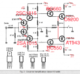
A great chance: the Classe A is a 4 step complementary parts amp.
Use the same transistors fo step 1 and 2, and other same for step 3 and 4.
Example: BC550/BC560 and BC560/BC550, TIP41/TIP42 and TIP42/TIP41.
Why: The (nearly) same current (exacter: curring, flow) of the parts are reflectet half waves related. And: you introduce only 2 x 2 instead of 4 x 2 different tonal characters. Result: a finer, more homogenic, more "dissolved" sound.
😉
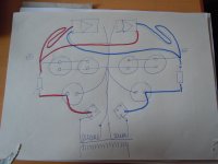
For maximum sound: resolution and homogeneity, in the case of Hiraga's Classe A, or Le Monstre - and also other half-wave amplifiers:
For maximum sound: resolution and homogeneity, in the case of Hiraga's Classe A, or Le Monstre - and also other half-wave amplifiers:
- Connect each half-wave amplifier to even just one secondary winding of the transformer - Two rectifier bridges or only two simple diodes required.
- With several parallel capacitors: route the voltage supply lines to the amplifiers in the opposite direction to the earth connection.
- Make sure that the cables to the amplifiers and power transistors are identical in length: per half wave and channel.
- Remove the thick copper bars and replace them with single wire, max. 1 mm diameter.
Attachments
- Home
- Amplifiers
- Solid State
- Which Output Transistors are best for Jean Hiraga Super Class A 30 W