Ah yeah, I forgot to swap them around, was working in a rushBefore the quality of the PCB pattern, it seems that the inverting input and non-inverting input of OP-AMP are reversed in both the circuit diagram and the board.
Will there be gerbers available for it ?Omicron construction, as mentioned before, is a single, all-through-hole, 78x108mm PCB that holds two amplification channels plus output filters and protection.
View attachment 1066330View attachment 1066333View attachment 1066334View attachment 1066341View attachment 1066342
Using one board for two channels simplifies proper grounding, which is essential - and I cannot stress this enough - for the distortion performance of any amplifier with single-ended input. It also makes it easy to use a single power supply for both channels; I believe using one power transformer per channel of even a high-performance headphone amplifier is unnecessary (and costly).
The power supply is on a separate, slightly larger (78x128mm), board:
View attachment 1066320View attachment 1066335View attachment 1066343
Both boards are designed for commonly available parts, including axial 0.25W metal film resistors, radial NP0 or film capacitors (5mm lead spacing), an Omron G6A small-signal relay, Aavid 5310 board-level heatsinks, and so on. Two handmade components are theb toroidal air core inductors for the output filters - I will discuss them in a separate post. The connectors are Molex KK254 or similar, but the boards will happily accommodate 0.1" screw terminal blocks, other 0.1" connectors, or bare wire.
Most parts, including the output transistors allow, broad substitution. One that I do not recommend replacing is the 5532 opamp. In testing, it demonstrated best overall performance and is strongly recommended. Having said that, other opamps with GBW of 8 to 16 MHz (e.g. OPA2134) may work, but one needs to check for stability and clean clipping. Even the TL072 works well. although its lower gain shows in the slightly higher distortion:
View attachment 1066339
Faster opamps (e.g. the 55MHz LM4562) require changes in the frequency compensation and are not recommended.
I have no plans to publish the gerbers. I do have a few spare PCBs - please PM me if interested.Will there be gerbers available for it ?
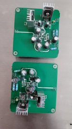
After much delay ive been able to get your circuit running but with 2 significant changes- the input opamp is non inverting and the 2 opamps are single types which has allowed for better layout with no crossing traces that i believe can be potential source of modulation> performance degradation.
The resulting circuit sounds flawless and works equally well. I used opa1641s. The claimed <140db probably holds true because this design sounds cleaner and smoother than anything ive built and that includes single opamp setups and well known discretes.
The resulting circuit sounds flawless and works equally well. I used opa1641s. The claimed <140db probably holds true because this design sounds cleaner and smoother than anything ive built and that includes single opamp setups and well known discretes.
Attachments

Congratulations!The resulting circuit sounds flawless and works equally well.
That should work fine with OPA1641 that you used. (TI took steps to make its input capacitance stable with applied common-mode input voltage.) Note that the vast majority of opamps will produce additional distortion in the non-inverting configuration.the input opamp is non inverting
Some of those building Omicron found its input impedance a little low, esp. with the crossfeed connected. There is an easy way to triple Omicron's input impedance by changing the values of the feedback and crossfeed network as follows:

If the input is connected directly to a volume control pot, then the higher input impedance will somewhat change the relationship between the knob position and the signal level. In testing that was hardly noticeable and caused no inconvenience.
If the input is connected directly to a volume control pot, then the higher input impedance will somewhat change the relationship between the knob position and the signal level. In testing that was hardly noticeable and caused no inconvenience.
Omicron has got a new (prototype) SMT board:

The size is 60×90mm - that's two amplifier channels, DC protection and the output filter. Most of the components are SMT, but in the packages easy to solder by hand - 1206, SOIC, SOT-23 and SOT-223. The only through hole components are connectors, relays, larger caps, and the (optional) LED. The output transistors are PZT2222 and PZT2907, the quiescent current is 25mA. The board serves as the heatsink.
Compared with the through-hole version, the crossfeed can now be switched on and off by a relay. Listening with the crossfeed on and off confirmed that a crossfeed is a must when listening with headphones.
Also, a line output is added - instead of the inductor, it uses a simple RCR filter and allows using Omicron as an extremely low distortion preamp.
I have not measured the distortion yet nor have I tried other opamps (currently, the board runs with two NE5532D's by TI).
Last edited:
I can't find the isolation inductor with that very impressive shape. How does it handle capacitive loads?
The inductor is there - on the photo, it's the black cube close to the connectors on the left. It is Murata's 78602 pulse transformer with triple identical windings (the idea is borrowed from @Nazar_lv). The leakage inductance plays the role of the isolation inductor, while the coupled inductance protects the amp from common mode EMI ingress.I can't find the isolation inductor
The line output bypasses the inductor and uses an RCR T-filter instead.
The prototype is stable with capacitive loads up to 10nF on the headphone output and with any capacitance on the line output. I am still working on it though.
Last edited:
Speaking of the inductor for the through-hole version of Omicron, here is how to make one.inductor with that very impressive shape
Start with about 32in/80cm of 22 AWG (0.6-0.7mm) magnet wire:

Wind half of it in a single layer coil on an approx. 0.25in (6-7mm) cylindrical former - a thick pencil with round cross section worked well:

Wind the other half in a separate single layer coil, going in the opposite direction along the length of the former:

Here I used two pencils, but it is not essential - one is enough.
Next, push the two coils together, interleaving turns from one with the turns from the other cool:

The result will be a single coil:

Expand the turns on one side, shaping it in a toroid:

Wrap the coil around the same former and expand the turns on the outer side so that the spacing between turns is more or less uniform:

That's it!

One may add a small cable tie inside for better stability.
How is this way of winding better? It greatly reduces the effect of the parasitic turn:

This reduces the inductive coupling between this inductor and other circuits, such as the power transformer or the sensitive input circuit of the amplifier.
alexcp thanks for the answer.
I thought that black cube corresponded to the DC-DC converter for the power supply.
I think the use of leakage inductance is an interesting idea.
There is only one black cube, but does that mean the three windings are each Lch, Rch and a short circuit?
I thought that black cube corresponded to the DC-DC converter for the power supply.
I think the use of leakage inductance is an interesting idea.
There is only one black cube, but does that mean the three windings are each Lch, Rch and a short circuit?
Left, right, and common (a.k.a. ground) - the latter is necessary to suppress common mode EMI ingress.the three windings are each Lch, Rch and a short circuit?
Thanks for showing how to make a detailed inductor.
Using a composite amplifier or TPC makes it possible to easily obtain distortion of -120dBc or less, but in the end, board patterns and mounting become obstacles. In particular, the placement of the output inductor is a critical issue, as it picks up the magnetic field resulting from the non-linear power supply current of the OPS. If that toroid form coil doesn't pick up external magnetic fields easily, I'd like to try it.
That was my primary concern.This reduces the inductive coupling between this inductor and other circuits, such as the power transformer or the sensitive input circuit of the lifier.
Using a composite amplifier or TPC makes it possible to easily obtain distortion of -120dBc or less, but in the end, board patterns and mounting become obstacles. In particular, the placement of the output inductor is a critical issue, as it picks up the magnetic field resulting from the non-linear power supply current of the OPS. If that toroid form coil doesn't pick up external magnetic fields easily, I'd like to try it.
Those obstacles are manageable. All the measurements in the post #11 were done post output filter, on the PCB shown in the first post of this thread - and they are an order of magnitude better than -120dBc.board patterns and mounting become obstacles. In particular, the placement of the output inductor is a critical issue
BTW I still have one blank PCB left. PM me if interested.
How can I force the "pgood" from trafo.
Omicron is running on my test bench with labor supplies.
Connecting minus supply doesn´t switch relais on...
Omicron is running on my test bench with labor supplies.
Connecting minus supply doesn´t switch relais on...
Connecting PGOOD to the negative rail or leaving PGOOD floating should enable the relay by closing Q53 (see the schematic in post #42). If it doesn't turn on with PGOOD disconnected, there must be a reason different from PGOOD. Make sure you soldered the LED correctly. If the LED is ok, check the DC voltages at the amplifier's output and at the comparators' inputs and outputs and post the results here. That should help with pinpointing the problem.Connecting minus supply doesn´t switch relais on...
I´m using a different relais because I had it 😉
It´s an Omron G5V-2-H1 12V, coil resitance 288Ohm, I~42mA, changed R58 to 390R
and changed the LED for 47R resistor.
Are the comparator outputs capable driving the relais?
And which values for R56/R57?
It´s an Omron G5V-2-H1 12V, coil resitance 288Ohm, I~42mA, changed R58 to 390R
and changed the LED for 47R resistor.
Are the comparator outputs capable driving the relais?
And which values for R56/R57?
If you use the same +/-17V rails, then the string of the relay, R58, the LED, Q51 and Q52 will see 34V. Disregarding the voltage drop on the transistors, the current will be 34/(288+390+47)=47mA. A little on the high side, but probably ok.It´s an Omron G5V-2-H1 12V, coil resitance 288Ohm, I~42mA, changed R58 to 390R and changed the LED for 47R resistor.
The comparators do not drive the relay direclty. They control the voltage across C53, which in turn controls Q51/Q52 (see post #34 for an explanation of how Omicron's protection works). In fact, should you remove the comparators, e.g. pull the LM339 out of its socket (if you use the socket like I do), there would be no DC protection, but turn-on delay would still work.Are the comparator outputs capable driving the relais?
Use what's on the schematic - 100kOhm and 33kOhm, respectively. Together, they set the threshold for the voltage across C53 at which Q51/Q52 open. Do not change them unless you know what you're doing and why.And which values for R56/R57?
It would be helpful if you measured the voltages around the comparator and Q51/Q52 and posted them here - this way, it would be easy to find where the problem is.
I have the rev D pcb and refered to the shematic from post #42 where Q51/53 are BS170 (DGS) types.
In Omicron protection explanation from post #34 2N7002 (SGD) were used.
I´ve used BS170. That might be the issue...
Another point: My headphones are low/mid 16Ohm cans. I pushed the bias to arround 100mA per channel (R13/14 from 47R to 120R) at +/-15V supply.
The bias differs arround 5mA from left to right channel. Is this tolerable or do I need to readjust? And I´ve used 2SC3421/2SA1358 instead BD139/140.
Will +/-12V supply are also sufficient? That will lower the heat.
- Home
- Amplifiers
- Headphone Systems
- Omicron, a compact headphone amp with -140dB distortion