The Dave Slagle implementation is exotic in the sense that it requires a very large headroom in the CCS, which cannot be allowed to clip within signal excursion, thus an extra high power dissipation in the CCS pass devices. Excellent if you're willing to pay the overhead, but not trivial to make any significant shift on the B/H curve. The advantage to be gained is to either/or/both shift the idling point towards zero crossing and/or/both to allow the saturation flattening to happen sooner for the same signal excursion, meaning a small core, meaning smaller parasitics, both C and leakage L. Good things for exotic designs but at a high thermal cost.
Taken near enough to the extreme of having signal excursion pass through B/H zero crossing, we come back to the issue from push-pull DC field cancelling amplifiers, the transition through the zero crossing's permeability burble. Since inductance is linearly related to permeability (and permeability is the slope of the B/H curve) primary (magnetizing) inductance has a dip, a burble through the zero crossing region. Although primary inductance only appears in parallel to the output valves' load, it's not totally insignificant.
All good fortune,
Chris

This looks to me like grid modulator (left tube) and oscillator (right tube).I’m in the middle of a field in countryside, so please forgive my sketch on “cheese paper” as we say in Italy. This is the basic idea, but I will search other threads you mentioned that already talked about this topic. I'm very interested.
View attachment 1092114
Taken near enough to the extreme of having signal excursion pass through B/H zero crossing, we come back to the issue from push-pull DC field cancelling amplifiers, the transition through the zero crossing's permeability burble. Since inductance is linearly related to permeability (and permeability is the slope of the B/H curve) primary (magnetizing) inductance has a dip, a burble through the zero crossing region. Although primary inductance only appears in parallel to the output valves' load, it's not totally insignificant.
Chris - could you kindly explain "permeability burble"? In a typical B-H loop, lines are straight at zero B crossing.
B/H curves are often conventionally drawn as a straight line through the zero axis, but actually have a flattening, a reduced slope, through zero crossing. See Partridge, etc. This effects the output valves' load line to the extent that primary (magnetizing) inductance does. At higher frequencies, and with lower source impedances, not so much. But not none.
All good fortune,
Chris
All good fortune,
Chris
A core in a PP output stage sits at nominally 0,0 for idle (assuming balanced plate currents), and any small signal transfer will be in 'that' zone of 0,0.
No, they are not. If it where the case the DC or AC (booth where done) pre magnetisation wouldn't be nessesairy for tape recording.Chris - could you kindly explain "permeability burble"? In a typical B-H loop, lines are straight at zero B crossing.
Mona
You could put a (magnetically "soft" ) Ferrite xfmr with the same turns ratio in series with the P-P OT primaries and secondary to eliminate most of the crossover permeability "burble". It would saturate out sooner than the iron core, but the iron would just continue on. Similar to the Nickel pin-striped OTs. One could get clever and put a thick E-I Ferrite "lam" in the iron OT stack, but it would probably crack when the bolts get tightened. (magnetic tape used magnetically "hard" coatings to hold the data)
Long time ago I suggested putting a thin layer of magnetically "hard" material in a toroid core, plated onto the surfaces of the iron strip used to wind a toroid core. Hit it with a potent magnetizing pulse at power-up to pre-magnetize the core with the opposite field to the SE DC field. (the core field lines jump the layer "gap" thru-out every lamination turn.) No cut gap needed for DC then.
Far simpler (for linearizing an OT) is an old Audio Precision patent (# 4614914) that effectively removes winding resistance from the OT primary by positive current FDBK. Using Negative resistance equal to the winding resistance. No voltage drop occurs in the OT signal transfer then, but the output tubes do need a small amount of extra headroom to provide the correction current. Essentially it puts enough extra signal drive into the output grids to just cancel the IR OT loss. Takes like 3 resistors to do it. You don't need a SE OT then, so no DC problem. Even the crossover permeability "burble" gets fixed, since a drop in permeability means an increase in magnetizing current, which the Pos current Fdbk automatically fixes.
Last edited:
The point with coordinates 0, 0 on the B-H curve is crossed only two times: first when AC is applied to transformer, and second when AC is turned off. Otherwise, with AC across the winding, zero B line is never crossed at the 0, 0 point (due to hysteresis), no matter how small is the AC voltage. Crossings at horizontal zero axis are always straight lines, so there is no "permeability burble".
There are two ways of referring to 0,0 imho. The origin is where 0=0.000... with no decimal point rounding and no need to identify units, and is effectively a concept or graphical reference point.
0,0 could also imply the measured value of incremental ac inductance as ac excitation becomes smaller and smaller, where the ac ripple on say a balanced PP amp becomes smaller and smaller. Being an ac measurement, the measured incremental inductance varies with ac magnitude and frequency.
0,0 could also imply the measured value of incremental ac inductance as ac excitation becomes smaller and smaller, where the ac ripple on say a balanced PP amp becomes smaller and smaller. Being an ac measurement, the measured incremental inductance varies with ac magnitude and frequency.
Do you see any reason why the AP patent wouldn't also apply to a push-pull output stage? If it would work the same way, partial-nickel cores could become history, and push-pull regain some respect.Far simpler (for linearizing an OT) is an old Audio Precision patent (# 4614914) that effectively removes winding resistance from the OT primary by positive current FDBK. Using Negative resistance equal to the winding resistance. No voltage drop occurs in the OT signal transfer then, but the output tubes do need a small amount of extra headroom to provide the correction current. Essentially it puts enough extra signal drive into the output grids to just cancel the IR OT loss. Takes like 3 resistors to do it. You don't need a SE OT then, so no DC problem. Even the crossover permeability "burble" gets fixed, since a drop in permeability means an increase in magnetizing current, which the Pos current Fdbk automatically fixes.
You've been proselytizing for this improved structure for a while. Maybe now more folk will be listening.
Much thanks, as always,
Chris
A few years back I presented my solution to the core saturation problem in a thread called "simple tube circuit transforming push- pull output transformer into single ended one" which can be found here. Readers proposed other solutions so it was quite interesting not just for me but for anyone interested in this subject.
A random idea popped im my mind - could you decrease the DC current flux density by permanent magnets around the core?
Oldish stuff....just to say, it has been done!
https://audioxpress.com/article/a-double-ended-two-channel-amp
Ad the end you find info on how to make self-compensating output trnasformer. In this case it was a good solution as it was meant to be used in 50W SE amp using three 6C33 in parallel on each channed for about 700 mA DC current...
For a standard SE running up to about 200 mA DC current I don't think it is necessary or better performing.
Do you see any reason why the AP patent wouldn't also apply to a push-pull output stage? If it would work the same way, partial-nickel cores could become history, and push-pull regain some respect.
It should work for P-P too, however most P-P OTs don't have equal winding resistance in the two P-P halves. So each P-P side will need the Pos. current (sensed) Fdbk resistor tweaked to match up, or one of the two primary windings could use a resistance fill-out resistor in series to equalize them.
--------------------------------------------------------
The AudioExpress article is interesting, but needs a very custom xfmr.
I would suggest the method Westinghouse (and others) used. They put the common signal thru a P-P OT and the L-R difference signal thru a tiny SE OT.
L and R outputs were formed by adding or subtracting the difference signal outputs with the common signal output. No loss of bass with this scheme. Complete L R separation for imaging accuracy.
Another variant puts both channels thru the same center gapped P-P OT core, with common mode using non gapped P-P mode around the E-I perimeter and difference mode using the gapped center leg in SE mode. Usually with just two output tubes for all, multiplexed by differential mode drive for P-P and the SE mode using common mode in the tube drives. Often called "multiplexed amplifiers". Generally considered a low cost solution.
---------------------------------------------------------
A random idea popped im my mind - could you decrease the DC current flux density by permanent magnets around the core?
The problem here is the magnet flux needs to be put into the DC flux path. External magnets won't do that. You could get them to DC cancel half the total path, but that's not working for the other half.
KeesB: link? nothing comes up in search
Last edited:
I think it’s this one:
https://www.diyaudio.com/community/...put-transformer-into-single-ended-one.341096/
https://www.diyaudio.com/community/...put-transformer-into-single-ended-one.341096/
That is consistent with the "burble" near (0,0) in the normal magnetisation curve (Landee, Davis & Albrecht, 1957, Electronic Deisgners' Handbook, Figure 14.3).The point with coordinates 0, 0 on the B-H curve is crossed only two times: first when AC is applied to transformer, and second when AC is turned off. Otherwise, with AC across the winding, zero B line is never crossed at the 0, 0 point (due to hysteresis), no matter how small is the AC voltage. Crossings at horizontal zero axis are always straight lines, so there is no "permeability burble".
Attachments
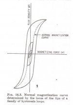
But, as I posted, normal magnetization curve only occurs when magnetizing force is applied to unmagnetized core. It happens only during the first and during the last period of applied AC, i.e. when transformer is turned on or off. With AC steadily across primary, magnetization follows not normal curve, but hysteresis loop. No burbles.That is consistent with the "burble" near (0,0) in the normal magnetisation curve (Landee, Davis & Albrecht, 1957, Electronic Deisgners' Handbook, Figure 14.3).
- Home
- Amplifiers
- Tubes / Valves
- A way to help core saturation in SE