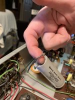
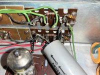
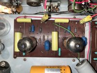
Hey guys. I have a dyna PAS3x that is OEM. I just acquired another one that has the Alstine mods done to it. I am not too familiar with the Alstine unit. I have read a lot about them, but this is the 1st time i’ve been inside one. My question is this: one large capacitor has come unsoldered at one end. By looking at the pics included, can anyone tell me where to resolder the loose connection. I have looked at every pic on the net, but cannot find an image that is the same as the layout of my unit. All of the tubes light up except the two 02AX7A’s shown in pic #1. It seems that the loose connection will power these two tubes, but i do not see where it might have been connected. I will provide more pics, videos or live facetime with anyone who might help. Thanks a million. Jeff
Attachments

You will be better off by rewiring as per the dynaco manual.
See http://www.audioregenesis.com/documents/PAS_Phono.pdf for a serious discussion.
See http://www.audioregenesis.com/documents/PAS_Phono.pdf for a serious discussion.
How is that relevant to the Van Alstine mod?You will be better off by rewiring as per the dynaco manual.
See http://www.audioregenesis.com/documents/PAS_Phono.pdf for a serious discussion.
You might be able to get info from Frank Van Alstine at www.avahifi.com. That's a pretty old version I think. I don't know if he still sells upgrade kits or just rebuilds as a service.
The author is discussing a van alstein modded pas. My suggestion is to rewire as original PASHow is that relevant to the Van Alstine mod?
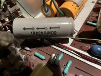
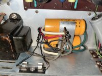
Just guessing: the cap is a 80uF 450V, so it should belong to the power supply; the loose wire is from the negative side of the cap, so it should go to ground. That doesn't explain why half of the tubes don't light up, so you may have another prob elsewhere.
Re.: "originality": there's quite a following for the Dynaco stuff, so making it appear original could make sense if resale if the goal. As for music enjoyment, the PAS3 is a lousy design to meet a price tag, that's why there's so many mods on the market.
Re.: "originality": there's quite a following for the Dynaco stuff, so making it appear original could make sense if resale if the goal. As for music enjoyment, the PAS3 is a lousy design to meet a price tag, that's why there's so many mods on the market.
Well, the van alstein is not one of these that enhances the sound quality. Best bet for good sound is toJust guessing: the cap is a 80uF 450V, so it should belong to the power supply; the loose wire is from the negative side of the cap, so it should go to ground. That doesn't explain why half of the tubes don't light up, so you may have another prob elsewhere.
Re.: "originality": there's quite a following for the Dynaco stuff, so making it appear original could make sense if resale if the goal. As for music enjoyment, the PAS3 is a lousy design to meet a price tag, that's why there's so many mods on the market.
restore to original design.(and maybe get new ECC83 tubes )
I don't see that anywhere in the article. It looks like a Curcio mod: http://www.curcioaudio.com/Dynaco PAS RIAA EQ Correction Mod.pdf.The author is discussing a van alstein modded pas. My suggestion is to rewire as original PAS
I'm not sure "by the numbers" if one circuit could be said to be better than the other. A subsonic peak (particularly problematic in a phono preamp) vs. an early bass rolloff, but more even response otherwise. It kind of depends on what you need/want.
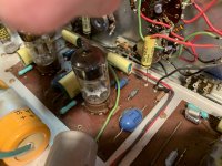
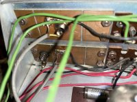
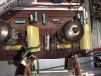
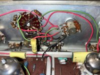
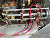
zung, you are correct. that is exactly what to cap is. i can solder well, but not sure what spot to connect the loose ended wire running off of the cap. Here are more pics. if you can spot where is connect it to, please mark on the pic where x marks the spot. thanksJust guessing: the cap is a 80uF 450V, so it should belong to the power supply; the loose wire is from the negative side of the cap, so it should go to ground. That doesn't explain why half of the tubes don't light up, so you may have another prob elsewhere.
Re.: "originality": there's quite a following for the Dynaco stuff, so making it appear original could make sense if resale if the goal. As for music enjoyment, the PAS3 is a lousy design to meet a price tag, that's why there's so many mods on the market.
Attachments
-
 41847007-876D-4D0F-A19B-61CBCADEC2D5.jpeg403.3 KB · Views: 65
 -
 C94D725B-9C4C-4E9B-B97B-4DF6FE6B4CB0.jpeg521.5 KB · Views: 57
 -
 D5D85483-744F-4F9F-8685-E607BE64C67E.jpeg452.8 KB · Views: 66
 -
 3ED381D7-B884-4D8A-80D4-6049EF957EAA.jpeg464.1 KB · Views: 56
 -
 E3EEEAE0-26B8-4CAE-98EC-28C9B32F5AAA.jpeg506.6 KB · Views: 68
 -
 FF4456B5-0CD1-4F8B-99AA-1305B13E6324.jpeg557.6 KB · Views: 59
 -
 ED57F629-A5BA-4529-9188-AA30DA79EA7F.jpeg608.8 KB · Views: 56
 -
 1260D8FB-E7E2-4A4A-8D5B-E31B8865A438.jpeg493.3 KB · Views: 65
 -
 F4BA7C4C-8397-4DC6-8836-E3C3D485C18A.jpeg475.7 KB · Views: 66
 -
 2A931689-F134-4BAE-945C-5E0C5FC3F7D1.jpeg444 KB · Views: 61
 -
 853D07AF-11A2-43BE-85D5-245212EF15EF.jpeg499.1 KB · Views: 61
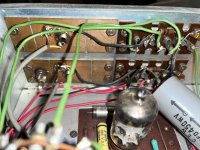
Lemme get this right: initially, the negative (-) side of the cap got unsoldered; you soldered it back, and somehow the positive (+) side got unsoldered, and you don't know where it goes. Right?
The morale of the story is:

The morale of the story is:
- Always take pics before and after
- If the (+) got loose by itself, you may question the quality of the solder joints, and you may want to reflow every joints, if you think you can do better. This may also cure the heater problem.
- Home
- Amplifiers
- Tubes / Valves
- PAS3x Van Alstine Modded question: